

Overview
If, like me, you just acquired an old CCTV camera or a Pan/Tilt/Zoom (PTZ) mount and want to press it into service, you will need some means of controlling it
The DIY 'standard' is, of course, the Open Source iSpy software. The problem is, whilst iSpy supports the more modern 'IP' (Ethernet/Internet connected) camera it has no support for the older cameras controlled by serial link.

One way around this is to 'convert' your serial camera into an IP camera using a Raspberry Pi.

However this seems a little like 'overkill' - you can use the Pi Zero / Zero W to keep costs down (the RS485 interface is easy enough, and you will, no doubt, run both Pi and camera off the same 24v PoE supply) but will still need a PC / Laptop to run the iSpy software

So - how about a PIC hand-held controller solution ?
Analogue CCTV camera PTZ (Pan, Tilt, Zoom) control
A CCTV PTZ controller sends signals along a RS485 serial link (usually 4800 or 9600 baud) that adjusts the camera 'pointing direction' (Pan and Tilt) and Zoom, along with some other camera control settings (Iris, Focus). Most control units can also set up 'zones' (for 'auto-patrol' = unattended scanning) operation
All controllers come with a joystick. A '2D' joystick controls up/down + left/right = Pan and Tilt. The arm of a '3D' joystick can be 'twisted' clockwise and anti-clockwise to control the Zoom.

Typically, the joystick up/down and left/right controls the camera mount 'speed of movement' in the pan and tilt direction, rather than actual position = so it is 'biased' (i.e. spring loaded) to return to the center 'stop' position when released.

Most units have multiple other buttons to control various other camera mount settings, and some even have a 2x16 character display.

Typically there is no control over camera AV 'mode' (they come preset to PAL or NTSC) or frame rate (PAL is usually 25fps, NTSC 30). The camera video is sent as an analogue ('AV') stream via a totally separate co-ax cable. There is an older standard that controls the camera mount by sending signals 'up the co-ax' (video cable), however this complicates the reciever end (almost all displays with a RCA AV socket will display the CCTV video picture, whilst 'up the cable' interferrence withh prevent this).

The industry standard RS485 CCTV control protocol is Pelco (Pelco-D, Pelco-P, Pelco-D1, Pelco-P1), with Pelco-P being the most common for the older analogue units.

Each Pelco-P command is 8 bytes long. Each byte is sent using a no parity, one start bit, one stop bit. The recommended baud rate is 4800(4800,8,N,1,1).

Each command consists of a 'start byte' (0xA0), followed by the Camera ID (0x00 - 0xFF), then 4 data bytes, an End byte (0xAF) and finally the Checksum byte (yes, the checksum is sent after the 'end byte' ...)
Note that even in the 'Extended' command set (which is used to setup the 'auto-scan' locations), Pelco P has no control over the video data stream (other than 'on' / 'off' and 'send test pattern'). So the video data stream is 'fixed' by the camera itself = i.e. it's PAL or NTSC, 25 or 30fps
Whilst you can't change the exposure time, there is nothing to stop the 'receiving unit' from 'frame stacking' etc.
The Checksum is the XOR of the 5 bytes 2-6 (i.e. the Camera ID and 4 data bytes)
Basic command set
Data byte 1 bits are assigned as follows :-
b7 = 0
b6 = Camera on ?
b5 = Autosocan On (means perform a pre-programmed sweep)
b4 = Camera off ?
b3 = Iris close
b3 = Iris open
b1 = Focus near
b0 = Focus far
Data byte 2 bits are assigned as follows :-
b7 = 0
b6 = Zoom wide
b5 = Zoom tele
b4 = Tilt down
b3 = Tilt up
b3 = Pan left
b1 = Pan right
b0 = 0
Data byte 3 = 0x00 or Pan speed 0x00-0x3F (0x20 = 'normal speed'), 0x40 = Turbo
Data byte 4 = 0x00 or Tilt speed 0x00-0x3F
Note: on receipt of a command (Iris/Focus/Zoom/Tilt/Pan) command, the camera will just keep moving until it's told to stop
Some Pelco-P command string examples (for "Camera 1" = address 0x00) :-
Pan Left at normal speed: A0 00 00 04 20 00 AF 2B
Pan Right at normal speed: A0 00 00 02 20 00 AF 2D
Tilt Up at normal speed: A0 00 00 08 00 20 AF 27
Tilt Down at normal speed: A0 00 00 10 00 20 AF 3F
Stop all actions (Pan / Tilt / Zoom / Iris etc.): A0 00 00 00 00 00 AF 0F
Note: depending on the model, some camera mounts will respond by sending back Acknowledgement data (so you need to 'tri-state' your transmitter after sending)
For more commands, see here
Using the PIC10F206
The PIC10F206 has only 4 i/o lines - and at least 1 of those will have to be 'reserved' to communicate with the CCTV camera (leaving only 3 for the actual control joystick/buttons/LEDs) - so why use it ? Well, CPC 'remaindered' their stock at 25p each, so grabbing a few dozen was irresistible :-)
The 10F206 chip does have a couple of advantages over some of the 'higher pin count' alternatives

First, it's got an internal 4MHz OSC (so delivers 1 MIPS performance with no external components).

Next the i/o pins have 'weak pull ups' (optional internal 'pull Hi' of 22k) which will also minimise the need for external components

Finally, it has one (8 bit) counter/timer and one internal 'analogue' comparator, which, when used together, can be used to form a basic A-D converter for 'resistance measurement'
For a PTZ controller, we will need measure the Pan and Tilt joystick variable resistance values and 3 on-off-on (center bias) toggle switches (Iris, Focus, and Zoom)
The 3 switches will be used for Zoom, Iris and Focus and have 2 'active' positions ('in', 'out') plus a center 'off'. Since only one switch + in/out position can be 'active' at any one time we only need to use a single PIC i/o pin (since absolute accuracy is not required, detecting logic 'Lo' will be 'good enough').

Movement of the joystick controls the speed of Pan and Tilt = the further the joystick is moved (from the center position), the faster the camera will move. Again, absolute accuracy is not needed, however since we have two i/o pins that can be used with the internal 'compare' circuit, we will use the internal Vref.

Since the camera can be moved 'diagonally', both Pan and Tilt can be active at the same time.

NOTE. Although only one switch can be 'on' at a time, it is possible that both the Zoom in or out may be active at the same time as Pan and Tilt.
PTZ joystick
The joystick 'center' position resistance is approx 5k (the pots. are 10k). The PIC will have to detect this during the power-on ('calibrate') cycle.
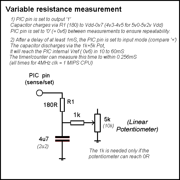
To measure the joystick position, it is necessary to measure the Potentiometer (variable) resistance. An explanation can be found on my Basic ADC resistance measurement page
Using the cheapest source (eBay) we can purchase an analogue '3D Joystick' such as "PS4 Wireless Controller 3D Joystick Analog Controller Part Replacement 2pcs" eBay 99p or, with button, "9Pin JoyStick Breakout Module Shield PS2 Joystick Game Controller" also 99p.
These joysticks have two small rotary ('trimmer' style) potentiometers built in, one each for 'up/down' and 'left/right' axis (the '3rd D' is a push-button that closes when the joystick arm is pressed down - which could be useful as a 'stop' command).

They have springs that will 'center' the stick position when released (so the controller thus has to discover the 'center resistance' and then measure the deviation, + / - from that position).

The potentiometers are only used over approx 90 degrees of travel and resistance varies wildly between units (I measured the center 'stop' position, 3k5 - 4k0, Max position, 4k7 - 5k0, Min position, 30R - 50R)
In the CCTV mount controller, the Joysticks is used to control the direction and speed of movement. Since the default biased center position = stop, it will be necessary to 'calibrate' the Joystick
Having the PIC do it's own calbration (rather than measuring the Joystick resistances 'off line' and modifying the code) will eliminate lots of other potetial inaccuracies (supply voltage, sense capacitor, series 1k/180 resistance etc)
PIC i/o pin assignment
The PIC has 4 i/o pins (GP0-3), GP0 and GP1 can both be used with the internal Vref, so these will be used to 'sense' the Pan and Tilt joystick potentiometers.
The only other full i/o pin, GP2 must be used as the RS485 serial link transmit output (and can 'double up' as a LED driver, see note 1).
This leaves GP3 (pin 8), which is an 'input only' pin and will be used as the 'button sensor'. To allow the 'button detect' capacitor to be charged up prior to a measurement, pin GP2 will have to be used (so GP2 'hi' output is fed to the capacitor, as well as illuminating the LED). To prevent a button press causing spurious values appearing on the RS485 serial link, a diode will be fitted.
Note 1. To avoid 'upsetting' the Joystick 'sense' code, GP2 is the only pin that can 'double up' as a 'feedback' LED driver. Since the RS485 bus 'idle' is 'hi', we can use the output '1' to drive the LED (switching the pin to input with waek=pull up will maintain bus idle but dim the LED)
Serial transmission
'Bit banging' at 4800 baud should be really easy with a 1MIPS CPU, especially as the other 3 i/o pin states will typically be 'output Hi' (recharging the resistance measurement capacitors) during transmission. Controlling the PTZ CCTV mount requires 'transmit' only (any response can be ignored). The only thing we need to remember is to tristate the pin when it's not in use (a Hi drive will light up the LED).
(-) RS422 RS485 drive with one PIC pin
RS422 / RS485 (differential) control with one PIC TTL output
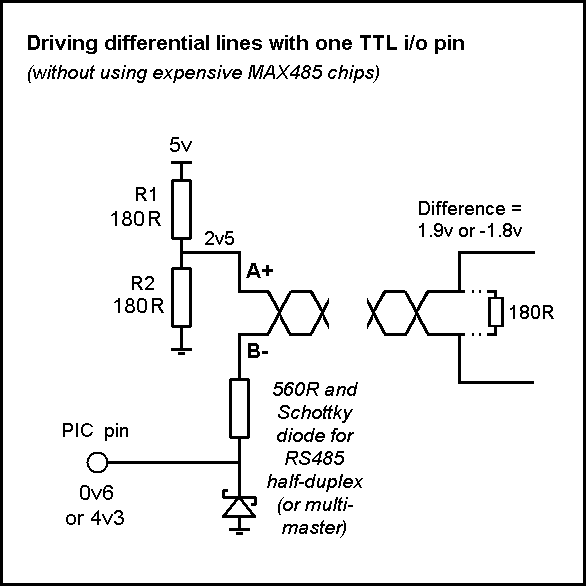
RS422 or single master full duplex RS485 (where the PIC is the only 'master')

Both RS422 and RS485 use a twisted pair cable to transmit signals over distances of up to 1km. Both use differential (A+, B-) signaling, but, unlike RS422, RS485 supports multiple 'masters' on the same cable.

Full duplex uses 2 pairs, one for Tx the other for Rx, however bi-directional 'half-duplex' is supported over a single pair (so is more common, especially for long cable runs, which can be up to 1km !). A ground (shield) wire (C) is usually present.

Driver voltages are typically +/-2.5v to +/-5v (max +/-6v) = the minimum 'specified' receiver difference is +/- 1.5v however most work down to +/-200mV (the max. voltage, referenced to chip ground, on any pin is -7 to +12). 'Idle' state is usually A more positive than B (which is taken as a '1') and (since the drivers are 'tri-state', idle is 'guaranteed' with the use of 'bias' resistors).

The receiver is simply looking for the 'difference' between the A+ and B- wires. A difference of +200mV is taken as a '1' and -200mV as a '0'. The actual voltage levels on the two wires are thus irrelevant, it being the 'difference' that counts. This means you can, in fact, 'get away with' using TTL 0,+5 and +5,0 as the two states (so long as you 'bias' the other wire to +2.5v).
Termination
The 'ideal' RS422/485 system consists of a single linear cable (no branches) with 120 ohm resistors connected across the 2 wires at each end of the cable. Sometimes additional termination resistors are added between each wire and ground/V+ or ground/V-, however this is typically done only for 'long line' usage.

RS485 can handle speeds of over 10 Mbits per second and line lengths of over 1 km. If you are operating anywhere near these values you must arrange your wiring close to the ideal and fit termination resistors HOWEVER at the more typical 4800/8600 baud and short distances, all the termaination resistors are often omitted.
The PIC drive
A PIC i/o pin will switch between 0v6 and Vdd-0v7 (for Vdd 5v, that's 4v3).

If one of the RS422/485 wires is held half way between these two values (i.e. at 2v45) and the other driven direct by the PIC pin, we get a difference of 2v45-0.6 = 1v85 (well above the 200mV minimum) and 2v45-4v3 = -1v85, again well below the -200mV minimum). In practice the 'mid point' will be 2.5v (giving us +1.9 and -1.8)

Note = the bus 'idle' state is PIC pin 'Hi' (so setting to 'input' mode (tri-state) using the weak internal pull-up (approx 22k) will work fine)

Multi-master and RS484 half-duplex considerations

The problem in a half-duplex or multi-master configuration is that the PIC is not the only device driving the lines.

Any other master (or a half-duplex slave) will likely use the standard +/-6v, and whilst 6v is not a big issue, -6v is.

In that situation, we have to add a Schottky diode (to prevent more than -0.3 appearing on the PIC i/o pin) plus a current limiting resistor (560R) to avoid blowing the remote transmitter (as it's -6v is 'shorted' to Gnd by the diode).

This, by the way, means the same PIC i/o pin used as a input can receive the slave transmissions (as the diode 0v3 limit = '0' and 6v = '1')
Usage
RS485 is used for the 'Profibus' and 'Modbus' interface standards, and extensively used for CCTV camera control (for example, Pelco-P)
This note last modified: 11th Aug 2017 10:54.
(+) Serial link - (9600 baud)
Power and connection
The cheapest source of twisted pair cable is, of course, Cat5e Ethernet cable, which is even cheaper than co-ax cable. So our controller needs an Ethernet RJ45 socket 'on board' (see note** below)
Since we have to run the Ethernet cable to the CCTV camera, we might as well use PoE (CCTV systems typically use 24v AC or DC at 1A)
To power the PIC we need 5v, so add a DC Power 'bullet' style socket for the 24v input and any simple 24v-5v regulator (even a 7805) and it's 'job done'.
Note** - a chassis mount RJ45 Ethernet socket will cost you a rip-off £10 (even on eBay). Instead you will have to go for a PCB mount (and poke it through a hole in your case). These can be had (on eBay) for less than 10p each (unshielded, "20pcs RJ45 8P8C Computer Internet Network PCB Jack Socket Black FK" £1.60) or about 25p each (shielded, "10Pcs New RJ45 Network Ethernet 8Pin PCB Mount Female Socket Connector" @ £2.54) == DO NOT go to Maplins who want £1.99 for each one (although, for once, they aren't quite charging 10x as much)
Putting it all together
p>The final circuit diagram can be found below: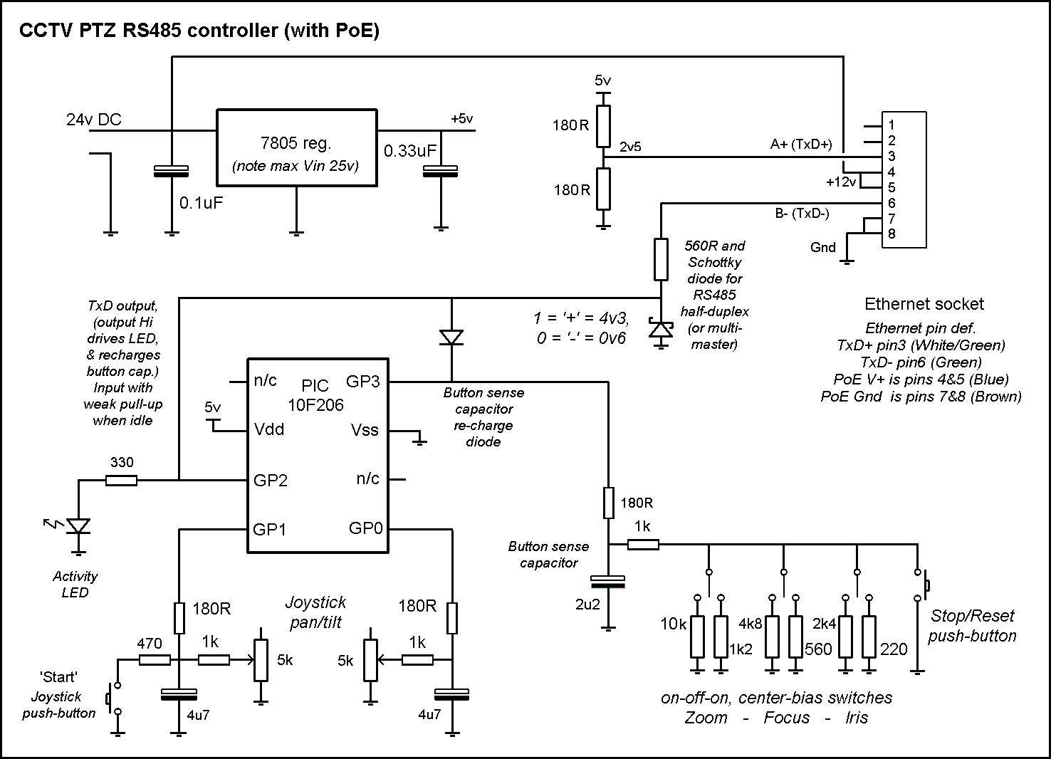
The control unit is powered from an external 24v DC source, so we don't need to worry about minimising power consumption = so no need for an 'off' switch. When power is turned on, the PIC will go into 'calibrate' mode and start by measuring the Joystick 'center' resistance values. It will then light the LED and wait for the user to move the joystick to the 'up' position, then 'down', then 'left' then 'right' (in order to calibrate the limit positions). For the actual code, see my next page.