

The PMSM/PMAC advantage
Unlike the DC Servo motor, a low voltage AC Permanent Magnet Synchronous Motor (PMSM) or Permanent Magnet AC (PMAC) motor does not require feedback to 'sense' the speed = a synchronous AC motor will 'always' be running at the AC drive frequency. Most will tolerate quite a high range of frequencies - indeed, just as a DC motor is 'ramped up to speed' (by applying a gradually increasing voltage) so the AC motor can be 'ramped up' from a low frequency to it's 'running speed' frequency.
High torque motors (for example, electric car motors) driving into heavy loads must be started 'gradually' with a low frequency drive, however the typical small motor will start just fine when driven at it's rated frequency, so long as the load doesn't cause it to stall.

Generally, AC motor speed* is independent of the applied voltage** and 'load' i.e. the motor will consume whatever current is needed to generate the torque required to maintain the it's speed.

Notes.
* A typical motor rated as "72rpm at 60Hz" is specified to run from 12rpm at 10Hz to 96rpm at 80Hz. Most small PMSM motors are rated at 50/60 Hz (for 0.8/1 rpm output), so you can guarantee these will support at least 10% speed variation (i.e. you can drive at 55Hz (= 0.9rpm) and get +/-5Hz (= +/- 0.1 rpm)).

** the rated torque does vary with voltage, however a typical 110vac motor will still be running (at 10% rated torque) at 30vac. If the load exceeds the rated torque the motor will start to 'slip' (i.e. slow down as the rotor fails to reach the next winding pole in time) rather than actually stop or 'stall' (in fact, chopping the AC voltage 'short' (with the thyristor controller) is a recognised way to slowing down such motors by inducing deliberate 'slip' (rotor pole skipping))

This makes the AC motor more useful in applications where the 'resistance' to movement can vary (due to load or gearing variations).

Note, however, when initially started from 'stopped', the current demand is 'infinite' (just like the DC motor)
When used for astronomy EQ mount head control, one massive advantage is that a typical 50Hz AC motor starts at 50x60 = 300 rpm (per pole) ... where-as the typical small DC motor 'no load' speed is in the region of 10,000 rpm (anything from 3,000 to 30,000 rpm is 'common') .... so the AC motor requires a LOT less gearing to get down to '1 rev. per day' :-)
There are two main disadvantages - one is that most small low cost AC motors are intended for fans/microwave turntables and run at 120/220v. The other is more devestating - almost all low cost motors (such as the TYC brand) are 'un-directional' i.e. can start up (and run) in either CW or CCW direction.

On the other hand, a 1 rpm (60Hz = 0.8 rpm motor at 50Hz) motor can be had for as low as £2.50 (eBay) - the 3 rpm rated "TYC50-AC-Synchronous-Motor-220V-3RPM-4W-8Kgf-cm-Torque-CCW-CW-LW" can be had for less than £2. You can find 12 vac motors for less than £1.50, however these are 5rpm...

Note - unless specifically stated otherwise, all the motors mentioned above can start up in either direction ! Many vendors will just state 'CW/CCW' (Clockwise / Counterclockwise) in the description, so be very careful if you want a Unidirectional motor (rather than a Undirectional one :-) ). Noe also, that instead of stalling, an AC motor will usually just reverse direction (which means a ratchet and pawl mechanism can be used on a small rotor to force it to start up in the same direction every time)
For more on the TYC50, see below
(-) TYC50 AC motor details
Photos from http://www.eng-tips.com/viewthread.cfm?qid=370926

The TYC-50 is typically sold as a 'microwave turntable' drive and sells for less than $5 on eBay (China). It measures about 50mm dia x 20mm deep, with an offset shaft about 7mm dia (1/4" maybe) by 12mm long.
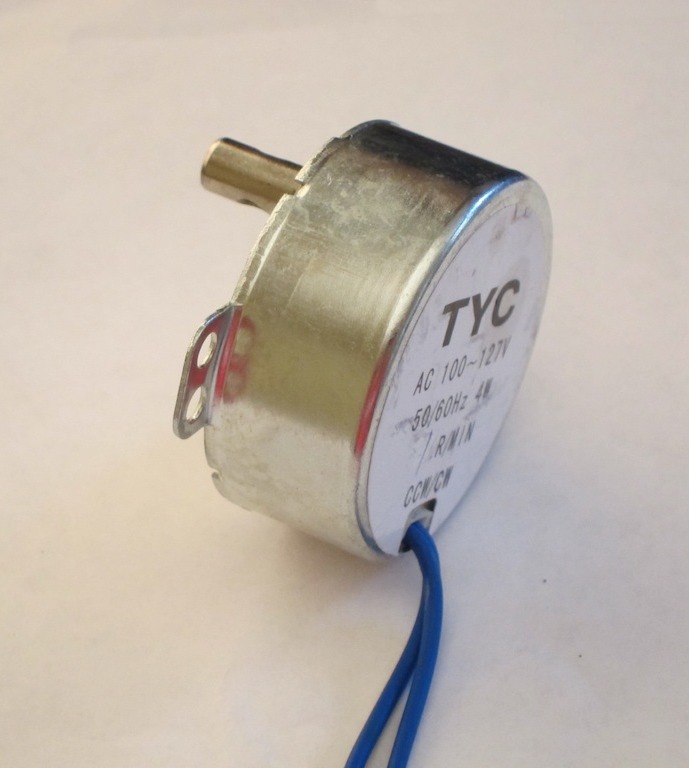
The 1rpm (110V 60Hz) version turns precisely at 1 rpm (from a US mains supply), and starts randomly in either direction (something that many vendors don't bother to make clear)
There's a transverse hole in the shaft through which I put a nail to get a good grip on the shaft and found I was unable to stall the motor by hand (I had no other way to actually measure the torque).
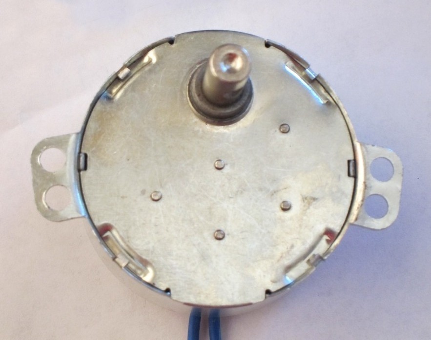
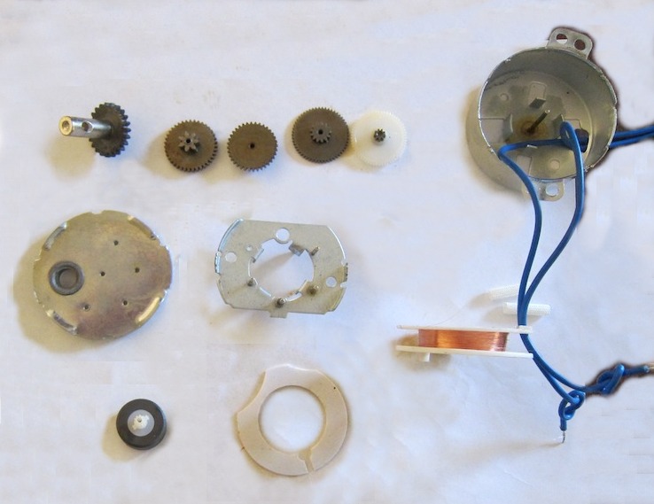
Looking at the bottom (shaft side) cover reveals 4 indents (with small tabs) around the circumference and 5 small 'dents' in a 3-2 pattern around the middle of the plate.

If you bend back the tabs and remove the cover, you reveal a five-stage gearbox, with a mixture of brass and plastic gears. The gears run on axles mounted on a sub-plate (at about half the depth of the housing) with the top ends being supported by the 'dents' in the cover piece.

Lifting out the gears reveals the sub-plate with a hole in the middle through which you can see the rotor below (of which more later).
The sub-plate is just friction-fit into the case, and is easily removed (after bending one of the edges down slightly to get a grip with the pliers).
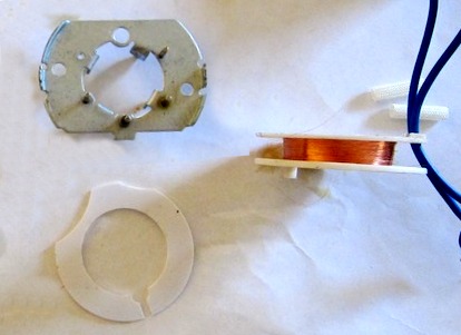
Below the plate is a plastic spacer. Removing the spacer revealed the drive coil (seen here side on). It's a single coil, wound axially, about a plastic bobbin about 6mm wide (inside dimension). The bobbin is separated from the central plate by a thick plastic spacer (of which more later).
The winding wire is extremely fine and very fragile - it broke away from the power leads the instant I handled it. It's wound on the bobbin to a depth of only about 3mm, though the bobbin looks like it would accommodate about 10mm ... except that the power leads ends also fit in this space, so call it 7mm max.
NOTE the coil is just a single winding == i.e. there is no 'start up' winding and no capacitor (to force it to turn in a predictable direction). However, see below re: rotor 'ears'.
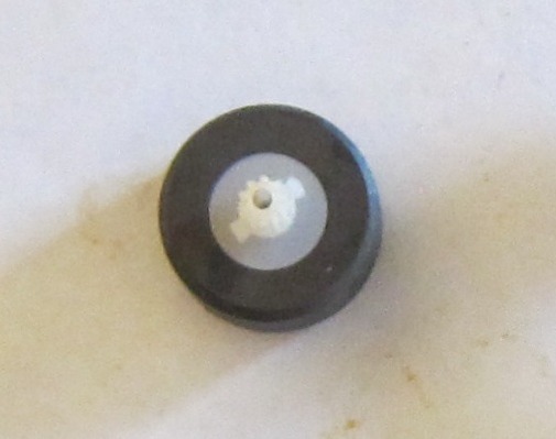
The rotor is a 'tubular' permanent ceramic magnet with a plastic output gear pressed or perhaps cemented into the center. The rotor lies centrally, in the lower half of the motor, below the plastic spacer, with its output pinion protruding into the upper, gearbox half. It rides on a full-length axle fastened to the bottom of the casing. The other end of this axle is supported by a detent in the cover piece (just like the gears).
It is noted that the rotor has two small 'ears' moulded into the gear flange. These extend about 1.5mm past the radius of the gear pinion.
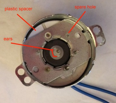
Now for some speculation. It's quite possible to mechanically 'force' an AC motor to start up in a specific direction. This is achieved with a sprung ratchet that prevents start up in the 'wrong' direction. It's entirely possible that the 'ears' on the rotor are designed to mate with a pawl mounted on the central divider plate = in the close-up left you will see an extra 'hole' in the plate where such a pawl could be mounted. Further, such a mechanism could be fitted in place of the thick plastic spacer (which appears to be positioned at exactly the right depth to pick up on the pinion 'ears').
On the other hand, perhaps the'spare' hole is just to support other gearing configurations, and the spacer is just to ensure everything fits together tightly.
This note last modified: 2nd Aug 2017 10:53.
Basic variable frequency drive (VFD)
The first point to note is, just like driving the DC motor, there is no need for any 'fancy' voltage control circuits (unless you are concerned about efficiency in multi-HP (multi-hundred Watt) motors). Motor windings are quite inductive, so we can drive them with a 'square wave' and they will sort themselves out (no need for any sort of 'sine wave' drive, although (if you must) you can simulate a sine wave using varibale frequency PWM to generate increasing/decreasing 'average' voltage on the motor windings).
NB. the term 'VFD' is usually taken to mean a variable frequency drive for 3 phase AC motors - when the term 'single phase' is used at all, it relates to induction motors with 'start winding' and 'split phase capacitor' and not single-phase permanent magnet motors.
The 'problem' is that we need an AC drive .. i.e. the voltage applied for each cycle has to go from '0' to '+ve', back to '0', '-ve' and finally back to 0. At the same time, digital devices like the PIC require only a single rail power supply (typically 5v).
The PIC system voltage is typically derived from a single voltage battery or from a +12 (or +24v) DC PoE input. It's quite possible to drive an AC motor from a single voltage DC supply - 'all' you have to do is 'reverse' the two wires across the supply for each half-cycle.

There are, however two drawbacks - first there's the need for a 'H' type power 'switch over' circuit (4 MOSFET's / thyristors or similar) and second, you need quite a complex 'lock out' circuit to prevent both sides of the 'H' turning on at the same time (and shorting out the power supply) = as might happen at power-on before the PIC i/o pins have been set and the code takes control.

You can get the standard L298N (dual full H bridge) for 99p or as part of a £1.50 (or less) interface board for the Arduino from eBay (China, post free) or purchase the chip alone from a UK distributor (eg CPC) for more than double that (£4.33). The L298N outputs can be driven at 25kHz or more, so PWM sine wave generation is quite possible, but they 'top out' at 35v .. so if your AC motor needs 110v (or 240v) you will have to look elsewhere.

Unfortunatly, almost every on-line resource I can find asssumes that a Permanent Magnet Synchronous Motor (PMSM) is driven by a 3-phase supply. You can even find a Microchip web page (and AN1660) on driving the PMSM which even suggest you use a PIC (in this case the dsPIC = which is well 'over the top') plus, as is often the case for many Microchip 'notes', you have to source an additional component = in this case it's the 'Inverter' (which is shown as a 3-phase output, despite the fact that almost 100% of low voltage AC motors are 2-phase)

The advantage of a 3 wire AC motor is, of course, that you can control the direction of rotation (you drive each of the 3 phases 'forward' by 60 degrees) - the disadvantage is that cheap/small 3-phase motors don't exist.
Dual voltage supply
If you are building your own drive circuit for a low voltage AC motor, it's easier if you run from a dual voltage (V+,0,V-) supply = that allows you to wire one of the motor drive wires to 0v and just switch the other between V+ and V-.
However, the standard PoE cable is wired for DC only (4 wires are used, but these are 'paired up' so you only have 2 wires available for power). The only 'simple' way to get dual (+/-) voltages out of a PoE supply is to use an AC feed-in voltage. This can be rectified at the device end to get the V+ and V- DC voltages (see diagram below)
Since only half-wave rectification is being used, 10,000uF (or more) caps will be needed, especially if you need voltages above the RMS level (if 24vac PoE, these will have to be rated for at least 35v)
An alternative to suppling AC via PoE is to use a pair of 'power-bank' 5v batteries - see my other notes on how to wire up both PoE and Power Bank in such a way that the batteries will 'take over' when PoE is removed (and PoE will recharge the Power Banks when connected)
Once you have dual supply voltages, you then need to drive the mptpr from V+ to V- and back again at the required frequency (55Hz +/-5Hz) to generate the AC wave.
Whilst it's easy enough to directly control a MOSFET from a PIC i/o pin to get the V+ drive, how do we drive to V- (when the PIC can't cope with =-ve voltages on it's i/o pins) ???

Well the trick is to use an 'opto-isolator' (which can be arranged in such a way that V- can never be 'active' when V+ is (also) being driven)

In fact, during normal operation, there must be some 'dead time' between V+ and V- drive ..