

Links to all my PIC tips, tricks and 'mini-project' notes
Whilst the mid-range PIC's can tackle many complex and otherwise almost impossible applications with ease, the challenge is to minimise cost by using the cheapest baseline PIC 'whenever possible'. Baseline PIC's can be had for less than 50p each = I purchased many 16F5x chips for between 40 and 50p each (mainly from CPC as 'remaindered' stock in their 'Bargain bin' section).
The even cheaper to use 12F675 (it has an internal OSC) can be found for as little as 20p (in Qty 10pcs, eBay), as can many other PIC's for less than £1 each. These PIC's are so cheap that you will soon start using them 'for everything' (especially as the PIC can often be used in place of a higher cost 'single function' digital chip - such as divider, ADC, PWM generator etc.) !
Buying the PIC in a 'TSOP' package is (sometimes) cheaper than the DIL/DIP package version = and whilst this costs you 10-20p extra for a mini-PCB TSOP-DIP 'converter', if you use a 'bigger' PCB than the PIC TSOP really needs you can mount other devices (resistors, caps, even osc. crystals) on the same board - and make use of the extra 'pin holes' to wire this up to the rest of your circuit
Below is a mix of programming tips and tricks, common circuit tricks and all the 'mini-projects' I've used the PIC for
I hope these details proves as useful to you as it does to me !
Below, click on the '+' to expand 'in place' (includes diagrams/images) or click the title URL (to view/download the text only version).
(+) 0004 Multi byte ADD - (24bit)
(+) 0005 new PIC 33 instruction set - (macros)
(+) 0006 Binary multiply methods
(+) 0007 8x8 - (multiply)
(+) 0008 8x16 - (multiply)
(+) 0011 Bi color LED driving
(-) 0012 One pin dual LED and button detect
Controlling 2 LED's and sensing a button press all using a single pin
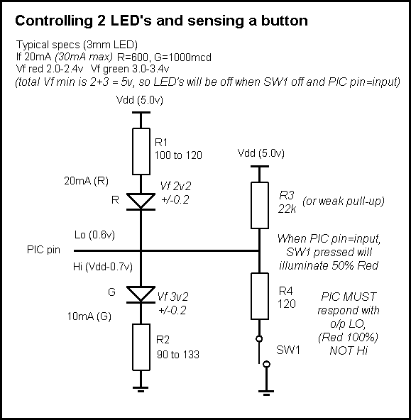
The 2 LEDs are driven 'as usual' (driving the PIC i/o pin Lo illuminates Red 20mA, driving Hi illuminates Green 10mA)
When no LED is lit (PIC i/o = input), the internal 'weak pull up' (or R3) of 22k will hold the pin Hi (there should be insufficient current to light G LED, but even is so, Green LED Vf will hold the pin to 3v min (and a '1' will be seen so long as the pin is 2v or above)
When the user presses the button, this will pull the PIC pin to 0v6 max. and a '0' will be seen. It will also pass approx 10mA through the Red LED (so approx 50% lit)
The danger is that the user may press the LED when the PIC is driving Hi (Green LED lit) - if this happens, the i/o pin will have to source 20mA via R4 + 10mA via G LED & R2 = 30mA total which is outside the PIC spec. (25mA) and risks burning the pin. So, to 'protect' against this, the PIC s/w code has to check for the button (switch the i/o pin between Green Hi drive and input sense) at regular intervals = the human eye won't spot anything over 30Hz.
Note, if 'feedback' is required (so the user knows their button press has been 'seen'), the PIC should respond by pulling the i/o pin Lo (so Red LED now 100%) and not Hi (Green) (unless 'strobing' is used to stay within the 25mA current limit)
This note last modified: 11th Aug 2017 10:54.