

Links to all my PIC tips, tricks and 'mini-project' notes
Whilst the mid-range PIC's can tackle many complex and otherwise almost impossible applications with ease, the challenge is to minimise cost by using the cheapest baseline PIC 'whenever possible'. Baseline PIC's can be had for less than 50p each = I purchased many 16F5x chips for between 40 and 50p each (mainly from CPC as 'remaindered' stock in their 'Bargain bin' section).
The even cheaper to use 12F675 (it has an internal OSC) can be found for as little as 20p (in Qty 10pcs, eBay), as can many other PIC's for less than £1 each. These PIC's are so cheap that you will soon start using them 'for everything' (especially as the PIC can often be used in place of a higher cost 'single function' digital chip - such as divider, ADC, PWM generator etc.) !
Buying the PIC in a 'TSOP' package is (sometimes) cheaper than the DIL/DIP package version = and whilst this costs you 10-20p extra for a mini-PCB TSOP-DIP 'converter', if you use a 'bigger' PCB than the PIC TSOP really needs you can mount other devices (resistors, caps, even osc. crystals) on the same board - and make use of the extra 'pin holes' to wire this up to the rest of your circuit
Below is a mix of programming tips and tricks, common circuit tricks and all the 'mini-projects' I've used the PIC for
I hope these details proves as useful to you as it does to me !
Below, click on the '+' to expand 'in place' (includes diagrams/images) or click the title URL (to view/download the text only version).
(+) 0004 Multi byte ADD - (24bit)
(+) 0005 new PIC 33 instruction set - (macros)
(+) 0006 Binary multiply methods
(+) 0007 8x8 - (multiply)
(+) 0008 8x16 - (multiply)
(+) 0011 Bi color LED driving
(+) 0012 One pin dual LED and button detect
(+) 0013 Input only multi button detect
(+) 001a One pin controls motor Fwd off Reverse
(+) 001c One pin controls 3 relays
(+) 0020 I2C bit banging
(+) 0021 I2C code
(+) 0021 Serial link - (9600 baud)
(+) 0028 RS422 RS485 drive with one PIC pin
(+) 0030 D to A conversion - (R2R DAC)
(+) 0031 Ternary DAC - (R3R)
(+) 0032 Hybrid ternary bit conversion - (code)
(+) 0035 Pulse Width Modulation - (PWM)
(+) 0040 Gearing axis sensor
(-) 005a TYC50 AC motor details
Photos from http://www.eng-tips.com/viewthread.cfm?qid=370926

The TYC-50 is typically sold as a 'microwave turntable' drive and sells for less than $5 on eBay (China). It measures about 50mm dia x 20mm deep, with an offset shaft about 7mm dia (1/4" maybe) by 12mm long.
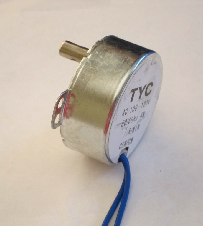
The 1rpm (110V 60Hz) version turns precisely at 1 rpm (from a US mains supply), and starts randomly in either direction (something that many vendors don't bother to make clear)
There's a transverse hole in the shaft through which I put a nail to get a good grip on the shaft and found I was unable to stall the motor by hand (I had no other way to actually measure the torque).
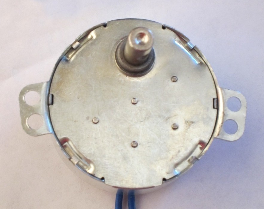
Looking at the bottom (shaft side) cover reveals 4 indents (with small tabs) around the circumference and 5 small 'dents' in a 3-2 pattern around the middle of the plate.

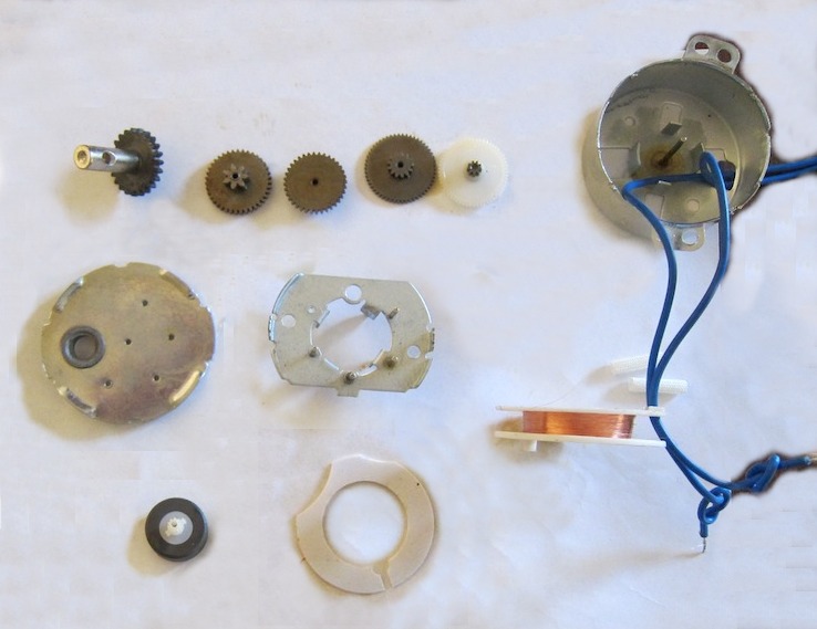
If you bend back the tabs and remove the cover, you reveal a five-stage gearbox, with a mixture of brass and plastic gears. The gears run on axles mounted on a sub-plate (at about half the depth of the housing) with the top ends being supported by the 'dents' in the cover piece.

Lifting out the gears reveals the sub-plate with a hole in the middle through which you can see the rotor below (of which more later).
The sub-plate is just friction-fit into the case, and is easily removed (after bending one of the edges down slightly to get a grip with the pliers).
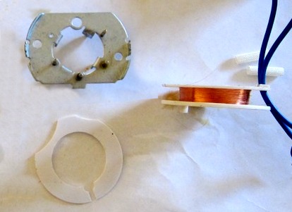
Below the plate is a plastic spacer. Removing the spacer revealed the drive coil (seen here side on). It's a single coil, wound axially, about a plastic bobbin about 6mm wide (inside dimension). The bobbin is separated from the central plate by a thick plastic spacer (of which more later).
The winding wire is extremely fine and very fragile - it broke away from the power leads the instant I handled it. It's wound on the bobbin to a depth of only about 3mm, though the bobbin looks like it would accommodate about 10mm ... except that the power leads ends also fit in this space, so call it 7mm max.
NOTE the coil is just a single winding == i.e. there is no 'start up' winding and no capacitor (to force it to turn in a predictable direction). However, see below re: rotor 'ears'.
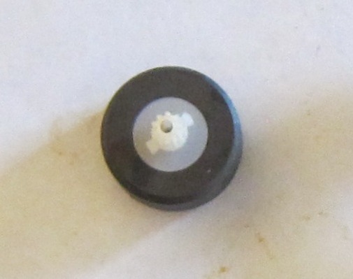
The rotor is a 'tubular' permanent ceramic magnet with a plastic output gear pressed or perhaps cemented into the center. The rotor lies centrally, in the lower half of the motor, below the plastic spacer, with its output pinion protruding into the upper, gearbox half. It rides on a full-length axle fastened to the bottom of the casing. The other end of this axle is supported by a detent in the cover piece (just like the gears).
It is noted that the rotor has two small 'ears' moulded into the gear flange. These extend about 1.5mm past the radius of the gear pinion.
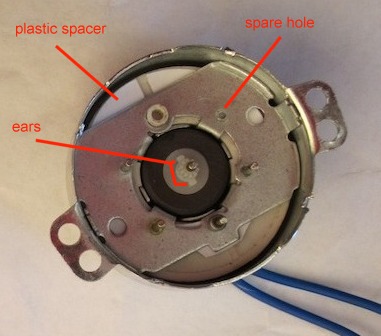
Now for some speculation. It's quite possible to mechanically 'force' an AC motor to start up in a specific direction. This is achieved with a sprung ratchet that prevents start up in the 'wrong' direction. It's entirely possible that the 'ears' on the rotor are designed to mate with a pawl mounted on the central divider plate = in the close-up left you will see an extra 'hole' in the plate where such a pawl could be mounted. Further, such a mechanism could be fitted in place of the thick plastic spacer (which appears to be positioned at exactly the right depth to pick up on the pinion 'ears').
On the other hand, perhaps the'spare' hole is just to support other gearing configurations, and the spacer is just to ensure everything fits together tightly.
This note last modified: 2nd Aug 2017 10:53.