Notes on using a Power Bank
You can now (mid 2016) purchase (very) cheap 'Power Bank' rechargeable battery packs which contain of one or more Lithium Polymer batteries (type 18650) with at least 700mA USB output.
Whilst these are designed to 'recharge' your smart phone / tablet, all you need to do is add a mains USB power-block (and, perhaps, a few diodes = see note 1). A basic 1200mAh UPS can now be built for less than £2.50 (£1 PowerBank, 50p diodes etc., £1 cable) !
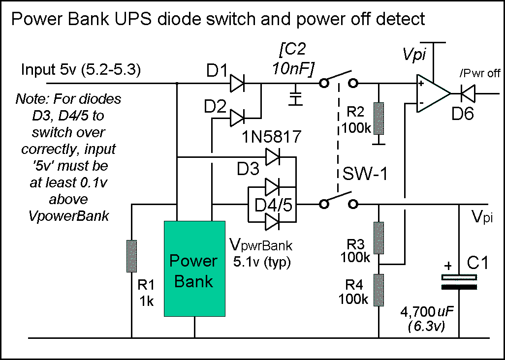
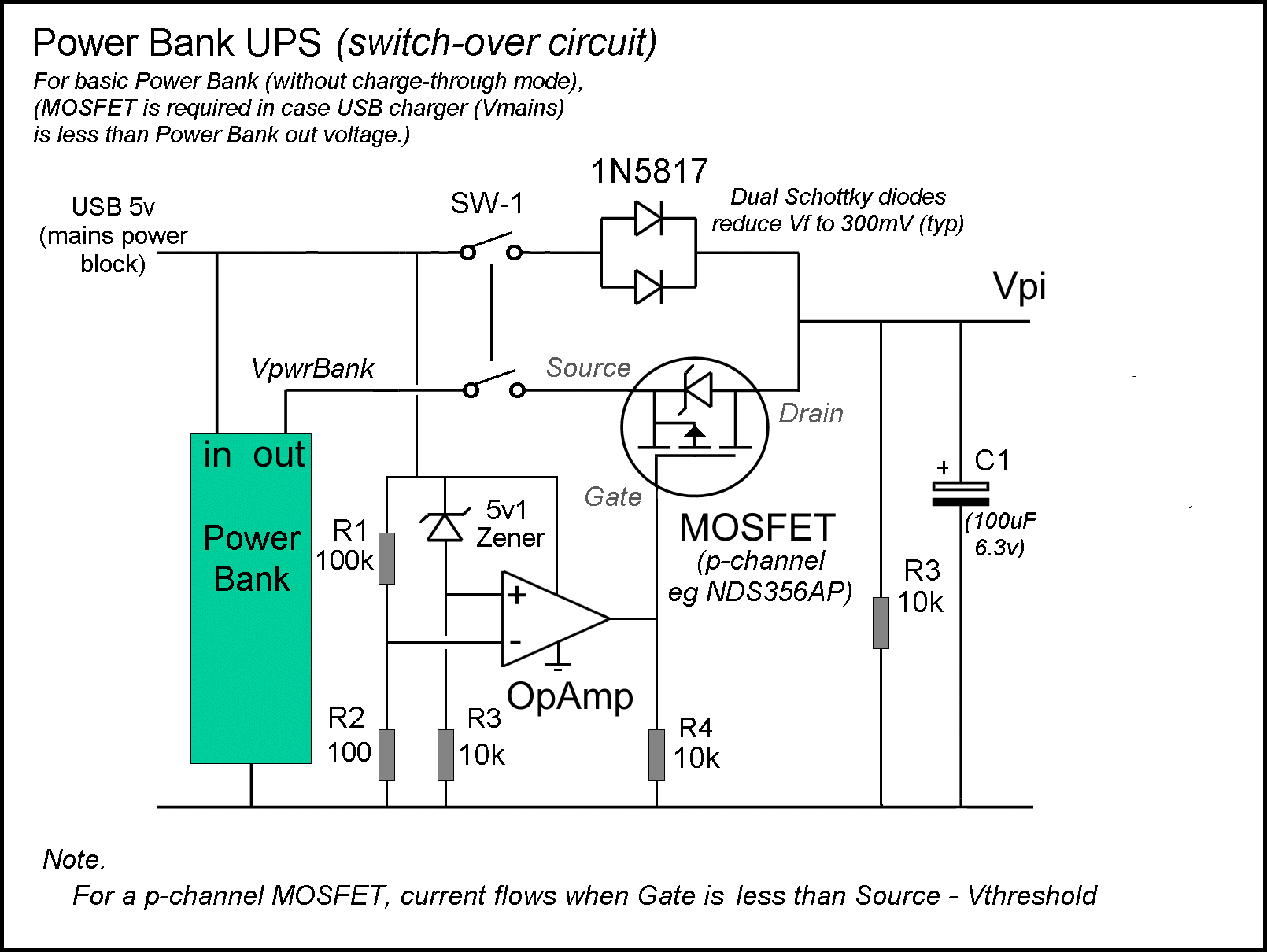
The basic UPS depends on diodes for 'switching' between 'main' and PowerBank, which is fine when you can adjust the 'main' voltage - as you can when using PoE. In other circumstances you may need to use the MOSFET based 'switch over' circuit (shown below = the MOSFET is used because the USB 'mains charger' might deliver lower voltage than the Power Bank - expand the "(+) MOSFET switch" link below for an explanation of how it works)
Notes.
1) A 'high end' PowerBank that supports 'pass-through charging' or as here) a 'Duo-Charge function' has an internal 'switch over' circuit, so you plug your 5v power block into the Power Bank input and power the Pi from the Power Bank output.

2) I have seen 'DIY' LiPO battery based UPS designs. Most use overpriced 'model aircraft' LiPO batteries and expect you to build your own 'charging' circuit. Don't be tempted - a standard small 'Power Bank' (with it's internal recharging circuit) will be come in at 1/10th the cost (even if you have to build your own MOSFET switch over circuit)

3) Power Bank capacity claims (especially on eBay) are not what they seem. The mAh specified is for the (3.2v) LiPO BATTERY INSIDE THE UNIT = to 'convert' that to USB power voltage (5.0v) you multiply by (3.2/5.0 =) 0.64. Further, every PowerBank must 'cut-off' when it gets to about 10% capacity remaining (as the internal charger can't recharge a completely flat LiPo cell).

So, when your single cell '2200mAh' unit arrives, you will discover it's actually 'rated' at no more than 1200mAh (and the dual cell '5,200 mAh' unit is really 2400mAh) :-) ).

Of course even a 1200mAh unit will keep the average Pi running for more than an hour (one user reports 3 Hrs out of a "5200 mAh" (2400mAh) unit, so you can expect over 90 mins for the 1200mAh, even with the camera connected to the Pi) = see below for Pi power usage.

Note, ALL the Power Banks I have ever found in UK retail shops turn out to be 'Made in China' = so don't waste your money on some 'branded' item (unless you like paying for very expensive sticky labels :-) )
A basic Power Bank UPS for the Pi Zero + camera can be assembled for less than £2. To see how I did this, click below :-
(+) diode switch
NOTE. When using a USB mains power-block that can't exceed the Power Bank voltage, the MOSFET switch (shown above) is needed. For an explanation of how this works, see below :-
(+) MOSFET switch
Interestingly, you can now find some cheap 'solar' equipped units (such as this 30000mAh-Solar-Charger-Battery-Power-Bank), however with the solar cells delivering a typical 1.5 Watts in bright sunlight with a Pi system consuming 5 Watts you will get 10 mins of use per half hour of solar charging - although it MIGHT just be up to running a Pi Zero + camera (1.3 watts))
Some Power Banks come with silly 'power buttons'. This can be an indication that they won't 'turn on' untill you press the button, so I generally avoid these types, however this RS branded unit which does have a 'power button' has been tested and works just fine. Another one known to work as a UPS is the LogiLink PA0064 Mobile Power Bank 2200mAh.
It's possible you may find a PowerBank that has to be 'switched on' or refuses to keep running at low current, however even the unit I found in the £1 shop (ITP Product Code H-28662) automatically turned on when I plugged in a 'load' (a USB memory stick) and kept 'running' even though the load current was < 1mA, only turning off a few seconds after the load was removed
Shutting down the Pi
The Pi needs to shut itself down before power is totally lost, ESPECIALLY if it's likely to be 'writing' to the SDHC card (as it will be in the case of a CCTV application when Ethernet comms is lost). For more details see :-
(-) Auto shut down
Shutting down the Pi
Shut down is by software 'command'. So what's needed is some way for the Pi to 'discover' that it's running on batteries and that the battery power is about to 'run out'. This does not have to be very 'clever', just 'reliable' (we don't want to shut down when there's plenty of power remaining and we don't want the Pi to be writing to the SDHC card when the power fails).
If you are using LiPO batteries, then you need to stop using them before they are totally flat (a LiPO battery can't be recharged from totally flat)

Most systems cut the LiPO off at 3.0v - and it's easy enough to wire up a Zener diode together with a 'Op Amp' style comparator that will 'flip the switch' when the battery reaches 3v0
To give the Pi a chance to shut itself down after power is lost, fit a decent capacitor across the 5v supply = if you trigger 'power lost' at 4.9v, then the Pi has until the capacitor drops below 4.75 to shut down cleanly
Pimoroni clean-shutdown code
If you wire your 'low power' detection to any GPIO pin between #4 and #27 (Hi = run, Lo = low power), you can use the existing clean-shutdown daemon from Pimoroni (for more details, see end of this page)
Detecting 'Mains lost'
From this 'How To' reference and the Raspberry Pi GPIO pins spec, it's obvious that the pin you choose to 'sense' the power state can be controlled by software to enable a 'default 0' (internal pull down resistance).
To 'detect' a 24v supply as 'mains-enabled' = 'logic 1', we have to 'pull-up' the pin above 1.3v (or 2v = reports differ) but it's vital not to exceed 3.3v (or at least limit the current to 0.5mA). The internal 'pull down' appears** to be about 50k. For a 24v supply to 'pull up' this up to 2v requires a 24/2x50k = 600k resistor. Current flow into the pin from the 24v would be 22/600k = .04mA (well within the .5mA limit)
**The internal pull down is specified at 40-65k.
So, the cost of 'detect mains lost' is approx 1p (one resistor) !
Ethernet loss as system shutdown
If your Pi is being used as part of a CCTV camera, and has PiPO (or other) battery backup, you might want to keep it running (and saving to SDHC card) even when the Ethernet cable is cut :-)
However if you are only using PoE (so Ethernet out = no power) or if the Pi is unable to funtion without the Ethernet, you ca use 'los of Ethernet' == 'power-down'.
Of cousre this is a lot easier with any model B Pi since they have built-in Ethernet. The Pi B+ and later have 2 LED's on the Ethernet socket itself :-

The Yellow LED is on for a 100-Mbps connection (and this off for 10mbs or when connection is lost) = same as '10M' LED on the B
Green LED is on for 'link established' and blinks for 'link activity' (and off for 'no link') = same as 'LNK' LED on the B

One Pi user has written custom software to monitor the Ethernet 'link' (the B 'system LEDS', which includes 2 Ethernet LEDS, '10M' or '100' and 'LINK' or 'LNK', are all accessible to the Python user, see here)
The 'best' choice on the B+ for 'Ethernet LAN down = power loss' would be to pick off the yellow LED (no modern Ethernet runs at 10mbs)
Detecting 'Low Battery'
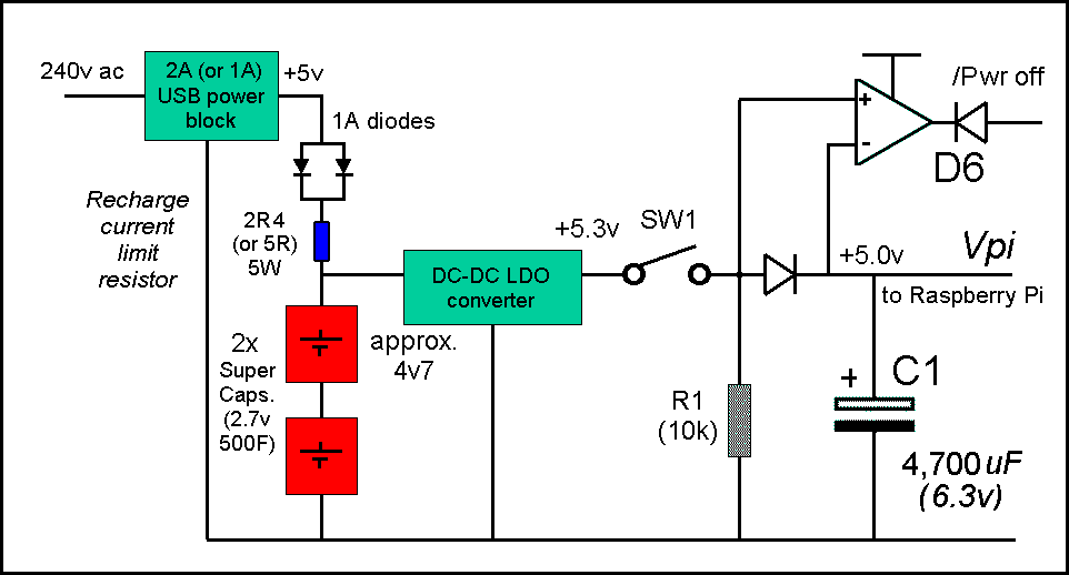
For PI's with battery backup, the 'obvious' approach to discovering that 'we are running out of (battery) power' is to monitor the battery voltage 'directly' with some sort of 'voltage detection' circuit (e.g. built around a 741 op-amp and a Zener diode etc. (see image)). An alternative is to use a special 'low voltage detector (LVD) chip' (such as the STM1061).
For example, NiMH battery voltage holds up very well during the discharge cycle with quite a steep voltage 'drop off' as it's capacity is used up, so the 'drop off' point is easy to spot.
An alternative approch is to montor the supply 'input' voltage and compare it to the Pi volts = as soon as input drops below Pi, the '/Pwr off' can be triggered. The drawback to this approach is that quite a decent capacitor is needed on the Pi 5v line to keep the Pi running long enough to shut itself down

If you can vary the voltage of the Pi 5v supply, adding a single diode in series with the Vpi power line means a simple 'comparator' can be used.
So long as the regulator is supplying power, the '+' input will be higher then the '-' and the comparator output 'hi' = 5v (D6 prevents this reaching the Pi i/o pin which is limited to 3v3 input max.).
When the regulator 'cuts out' and drops below Vpi (which is supported by capacitor C1) '/Pwr loss' goes 'Lo' (0v) and this is passed to the Pi i/o pin via D6.
If you are using LiPO batteries, then you need to stop using them before they are totally flat (a LiPO battery can't be recharged from the totally flat state). The typical cut-off point is 3v0 (so you need to 'trigger' the 'power-off' at 3v1 and have the Pi respond with a 'disconnect' when it shuts down). If you are using a Powerbank, this will 'switch itself off' as soon as it's internal battery voltage drops too low.

A more complex circuit is needed if you can't change the Pi power input voltage.
The circuit (right) 'monitors' both the supply input voltage and the actual battery voltage.
The comparator output will be Hi (5v) so long as the supply or battery '5v' is higher than the Pi 5v.
As soon as the power supply cuts off (and drops below the Vpi voltage) the comparator output will flip to the Lo (0v) state. Again, the capacitor on the Vpi line has to hold up long enough for the Pi to perform an 'orderly shut-down'.
One of the above approaches should work for all UPS designs.
This note last modified: 4th Jun 2017 15:27.
