

What are the basic components ?
The curved screw rod.
A 750mm length of standard M12 screw rod was purchased.
A 'template', of radius 400mm was constructed from a piece of card.
One end of the rod was clamped tight in the bench vice and the rod was then bent by hand to match the template.
The end damaged in the vice and the hand held end (which were essentially straight) were cut off leaving the just bent bit from the middle.
This turned out to be about 500mm long (enough for about 4 hours between 'resets' !)
The arms.
Cut two boards from suitable material. I used old Kitchen Cabinet - these are made from chipboard & seem to be more glue than wood :-) = they have stood up to years of moisture and changing temperatures in the kitchen before being retired to the garden shed for a couple of more years of weathering, so I figured they should be a good choice for occasional outdoor use. Another possible option is Marine Plywood. If you use plain wood you are going to have to seal it and varnish it before using it outdoors.
The arm length has to exceed 400mm (mine are approx 600mm). The board used needs to be wide enough to take a decent width of Hinge (mine is 250mm), and thick enough not to 'warp' easily under their own weight plus added weight of the camera etc. (mine is 3/4 inch or approx 20mm thick)
Ideally, 'reserve' the pre-cut end of each board as the "Hinge" end.
The Hinge.
Cut a piece of (brass) 'piano hinge' to the required size (in my case, a little under 250mm) .
DO NOT use normal door hinges - using one will result in a hinge that is so loose that the BarnDoor arms will slop all over the place and fitting two (or more) in perfect alignment is an exercise in precision that is not for the faint hearted :-) [ in general the KISS principle should be used wherever possible ]
You may be able to find 'standard door' sized plastic hinges .. one of these would be a good choice for smaller barn-doors.
Assembly - the arms
First you need to decide how to fit the Hinge to the arms.
Line up the ends of the two boards. It helps if these are the pre-cut ends :-)
Screw the hinge to one end and then the other. If the ends of the arms are cut 100% perfect you can screw the hinge onto the ends ( 1) in the diagram (below)
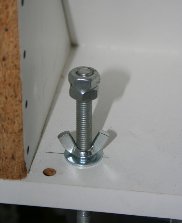
If in any doubt, take route 2 (as I did) - BUT make sure you use the screws that came with the hinge (or ones with recessed heads) which will allow the hinge to 'fully close' ....
... I didn't, as you can see in (image right) 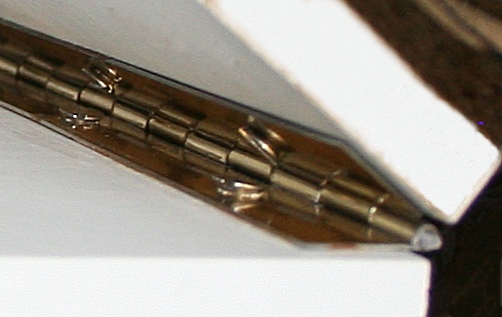 and as a result the 'fully closed' (start) position had to be set somewhat more 'open' than otherwise necessary.
In operation, the BarnDoor movable arm starts from the 'almost fully closed' position and is then gradually opened .. however the 'fully closed' start point is limited by the need for (manual) access to the drive wheel, so in practice there is little danger of the hinge screws running into one-another.
However, later, when motor drives are implemented, it will be seen that 'cut-out' switches will be required at both the 'fully closed' and 'fully open' limits - wired to cut the motor power (and thus prevent motor burn-out or the gear wheels stripping) for the inevitable occasions when the BarnDoor unit is left running unattended.
Measure exactly 400mm from the centre of the hinge axis up the board. Drill a pilot hole through from the 'inside'. Measure the other arm & mark the position - close the hinge and make sure the first pilot matches up with the just measured position. Drill through.
Enlarge the holes. Using a 12 mm wood drill, drill through the screw bolt hole in the Top arm - the screw bolt will be fixed to this arm, so a 'friction' fit hole is fine. Use a 13mm drill for the bottom arm hole - the bolt will need to pass through this arm and should not 'bind' onto the sides of the hole. Depending on how accurate the bolt screw was bent (and how thick the arm is) you may have to make this hole slightly oval :-)
Assembly - Base and adjustable feet
In usage we will need to ensure the correct Latitude angle. Assuming the angled mounting is constructed correctly (51.5 degrees - shown below), then all we need to do is ensure the base board is exactly flat.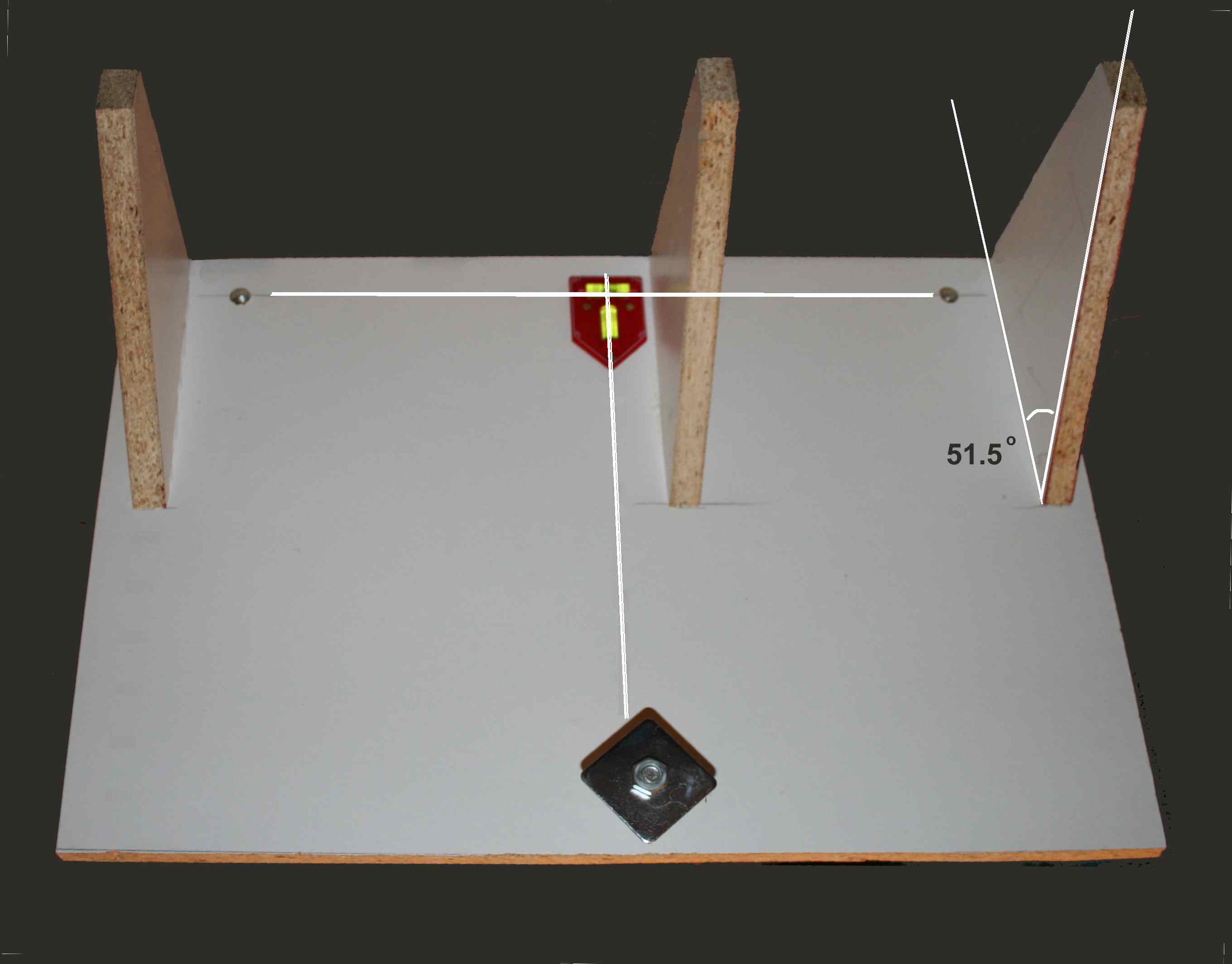
To achieve 'flatness' in the field, i.e. when balanced on a garden table, the base board is fitted with adjustable feet & a Spirit Level used.
Achieving balance will be a lot easier if we only need to adjust one foot at a time.
So the Base has 3 feet, with the 2 back feet positioned one at 'each end' under the moving arm (aligned 'along' the arm), and the 3rd in the middle of the front face.
The dual axis Spirit Level (red block in photo) is aligned at the junction of the "T" axis (white lines shown) made by the feet. Note that, to achieve this, the centre arm (51.5 degree) support has been shifted sideways, to the right as seen in the photo.
Note also that if you take this kit to another site in UK, all you need to do to change the 51.5 degree Latitude angle is to adjust the front leg.
The front (middle) foot is complete. You can just make out the press fit 'inserts' for the two back feet (at the ends of the "T" axis). The inserts are press-fitted fitted from the underside of the base, to avoid the weight of the unit acting so as to push them out again (see also later re: 'wobbly legs')
NOTE - although this design allows simple "up & down" adjustment for 'flatness', once this has been achieved, alignment to the North Celestial Pole (NCP) will require the whole unit to be rotated slightly (even assuming it is initially set-up perfectly facing (magnetic) North). A better design, to allow for easy rotational adjustment, would be to separate the Base (with it's Spirit level & adjustable feet) from the 51.5 degree 'angled' BarnDoor arm supports..
Fitting the BarnDoor Arms to the Base.
Before we fit the arms to the base we have to decide how much clearance we are going to need. This is not just for the arc rod 'sticking out' beyond the base but also for (manual) access to the drive nut.
We thus need to know if the Nut will be positioned on the top or bottom of the lower arm, and will the Hinge will be on the right or left (when aligned to the Pole Star) ? This is determined by the normal operation of the arms - will turning the Nut will "Open" (push apart) the arms or "Close" the (pull together) the arms ?
Plainly 'pushing open' is going to be a lot simpler - the Nut just has to push against the top side of the bottom arm. Pulling close either means the Nut pushes against the bottom side of the base arm (and the whole bolt & attached top arm is then free to drop through) or 'rides up' (and has to be restrained) on the top.
OK, so we want to 'push open' - on which side will the Hinge be ?
We need to counter-act the earths rotation. The earth rotates counter clock-wise, so (as you face North) mount must be moving clockwise (from West to East).
If the hinge is on your right (East, when polar aligned), then the BarnDoor 'opens' (in the Northern Hemisphere)
The screw rod goes through the centre of the drive Nut.... & if this to be driven by a Motor, this means a gear wheel attached to the Nut will need a centre hole of at least 12 mm (i.e. large enough to pass the M12 bolt). It MAY be possible to 'drill out' a Meccano gear wheel .... (as we shall see later).
The (almost) finished unit.
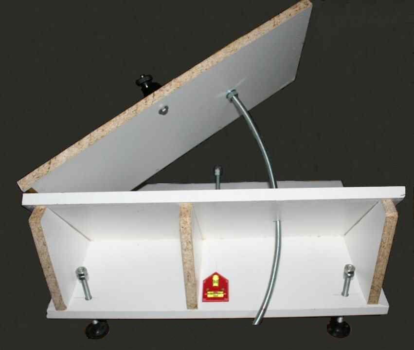 The curved screw guide rod only just clears the back of the base and when the top arm is (almost) fully closed, the end screw rod almost protrudes below the level of the feet.
The drive wheel (which will force the arms open) and clock timer are hidden by the fixed (bottom) arm, but the (standard screw) camera mount and dual axis spirit level (red) can both be seen in this view.
Yet to come :-
A magnetic compass (to aid initial North alignment) will be positioned just in front of the spirit level.
NB any compass has to be kept well away from any magnets used in the 'electric drive' circuit (see later) :-)
The finder scope, which will be mounted on the top (movable) arm near the hinge end.
Red LED lamp, used during set-up (to illuminate the compass and spirit level) and during manual operation (to illuminate the clock).
Rear view, after fitting the back feet and movable arms
Fixing wobbly feet :-)
 Unfortunately, it soon became apparent that the 'leg' bolts were rather a loose fit in the base screw thread 'inserts' and that the unit would wobble on it's feet at the slightest disturbance (a disaster, when taking long exposure time photo's).
To minimise wobble, wing nuts had to be fitted in order to 'clamp' the feet into position after levelling.
The screw inserts are fitted from the bottom, so tightening the wingnut 'clamps' the bolt into the chipboard
Mounting the alignment scope
Polar alignment Finder-scope
The ideal finder-scope would be a spotter scope (as used on a rifle range) fitted with an illuminated 'cross hair' reticule. Unfortunately such things can cost more than a professional 'GoTo' EQ telescope mount !
So we will have to 'make do' with whatever old / second hand / cheap eBay spotter scope can be found. Note, however, unless it has an angled (ideally, 90 degree) eyepiece it will be very difficult to use, even if the finished BarnDoor is used on a (highish) table.
A 'real' (ex-telescope) finder-scope is not ideal since these typically do not have a 90 degree (or interchangeable) eyepiece and are usually fixed with a type of 'bayonet shoe' mount, rather than the preferred (single) 'tripod bolt' mount. Unfortunately, we all have to make do with what's available and this is what my final build ended up with.
The finder-scope should be positioned as close as possible to the hinge and must be aligned PERFECTLY in-line with the hinge axis (plainly there is little point in lining up NCP to the finder scope if the finder-scope itself is not perfectly aligned to the Barn Door axis). This can be extremely difficult, not matter how carefully the mounting screw position(s) are measured and drilled. It is thus suggested that the scope be mounted using a single central bolt and some sort of 'adjustment' mechanism be devised.
Whatever means of adjustment is used, it must be possible to 'lock it off' (you won't have time to reset the finder every evening before starting your exposures)
So the first step is to attach the finder-scope to the BarnDoor (moving arm) with a single solid bolt as close as possible to the hinge. The bolt should be tight enough to prevent the finder 'slopping about' but still allow it to be 'pivoted' a little when forced. To this end, a non-slip (or 'spring') washer was fitted (over a plain washer).
Next we need to add some sort of 'side stops' that can be used to adjust the alignment .. the method I used involved a pair of 'kitchen cabinet construction' blocks ..
How do you align the finder-scope to the hinge axis ?
First the theory = IF the finder is aligned to the axis, THEN as the BarnDoor opens or closes, any object seen in the finder-scope will (should) be stationary (actually, since the finder-scope can not be exactly 'on top of' the hinge, the object will be seen to move in a tiny 'arc' as the finder-scope is moved about the hinge).
SO, to perform the alignment, all we need do is focus on some fixed object, at high magnification, and open/close the BarnDoor at high speed whilst adjusting the side stops. This can be done in daylight - when the minimum movement of any object in sight is achieved, the finder-scope is aligned with the axis.
So much for the basic build - click Next>> (on left) for the manual 'drive' ...