

Digital oscilloscope 'front ends'
If all you need to capture is 'audio' frequencies (i.e 20Hz-20kHz) then you can use the PC 'microphone' input ! However if you need to see lower frequencies (down to DC) and higher ones (up to 1MHz) then you will need some sort of DIY 'front end' sampling system
The higher the sampling frequency, the harder it is to build a DIY solution.

To get a decent view of a 'sinewave' you need to sample at about 10x the sinewave frequency - so a 1MHz input really needs at least 10Msps (Mega samples per second)
Achieving this is not easy = however transferring the data to the PC is even harder ! In most cases it's the data transfer that will 'bottleneck' your ADC = as a 'rule of thumb', you can get about 1mbs (100k bytes/s) via RS232 (serial pport), 1M byte/s via LPT (parallel prot) and perhaps 20 to 30M bytes/s via USB 2.0
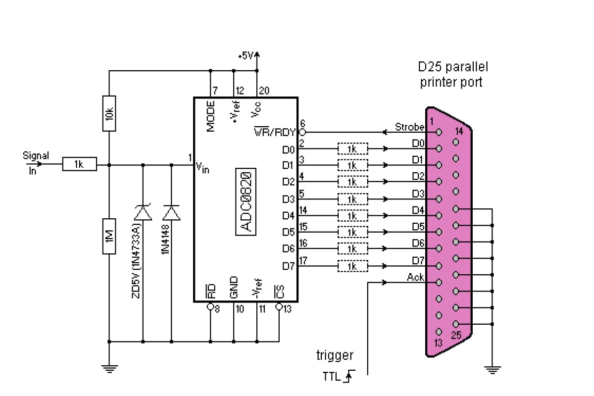
Even a simple low-end ADC chip - such as the ADC0820CCN / TLC0820 (8 bit A/D converter 20pin DIP) - delivers 667k sps (single channel) - which makes the Parallel Port a good choice.
In fact, the 8bit output of the ADC0820 can be wired direct to the parallel port pins (see diagram, right -- generating the (TTL level) sample 'trigger' (max 667kHz) is 'left to the user' :-) )
The analogue bit
If not using a kit, you will have to design your own analogue input stage. This can be a real pain :-)
A 'proper' oscilloscope probe has >1M ohm impedance (with < 2pf capacitance) and can handle a very wide range of voltages. The only practical way to achieve this is to use a switched resistor chain divider (to reduce the input signal voltage from a typical max +/- 250v down to a point where the rest of the circuits can cope (typ. +/- 2v5)) feeding an 'Op Amp' which 'buffers' the signal prior to the digital (ADC) stage
If the analogue op-amp is run from the same 5v DC supply as the digital ADC chip, you will need a 2v5 (Vcc/2 = virtual 0v) 'offset' and limit the op-amp input to +/-2v5 max.
To handle a range of input voltages, up to UK AC mains voltages, you need a 100x, 10x and 1x divider stange.
In practice, the probes will deliver 10x, so you actually need 10x, 1x and .1x divider (10:, 1:1, 1:10). This is achieved using the gain resistors (9M, 900k - which will need to be calibrarted for the actual probe '9M equivalent')
Note that, to avoid the +/-25v damaging the op-amp, zener diodes (not shown) must be fitted to the op-amp '-' inputThe Op-amps
The major problem is that you will want to support input voltages up to 250v ac and down to perhaps 250mV
The obvious way to support 250v is via a 'x10' probe (which will switch a 9M ohm resistor into the path, so when terminated with 1M ohm at the osc. input, this will drop the Vin from 250v to 25v - NB. in x1 mode, the 9M becomes about 330ohms DC) Even so, internally your circuit is likley running at +/0 2v5 and will quickly get upset if presented with +/- 25v ! So a pair of 2v5 Zenor diodes will be needed to protect the inputs of each channel op-amp. Whilst this minimises the chance of electricution during testing, you now have to cope with voltages as low as +/- 25mV. The Op-amps will need to cover 3 decades = 1:1 (250v sample, 25v input), 10:1 (25v sample, 250mV input) to 100:1 (250mV sample, 25mV input) A dual gang 3 position mechanical switch can provide the switching, however this will introduce unwanted capacitance and that will reduce the effective probe bandwidth by as muchas 10x (which is why the alternative is to provide 3 input sockets marked 'Low' 'Med' 'High' range). Since this design will 'top out' at less than 1MHz, it doesn't matter in the typical 50MHz bandwidth probe is 'slugged' down to 5 MHz and the switched approch will work just fine. Note that some means of 'calibrating' the 'virtual 0v' value (2v5 nominal) will be needed, either in software (or the ADC hardware)The digital bit
Programming a PIC
Commercial PIC programming tools cost the usual 'arm and a leg', however it turns out that programming the PIC 'Flash' memory is surprisingly easy
You can build one of the many DIY PC serial port based designs or purchase one of a number of kits, however it's hard to beat the price of the "USB K150 PIC Automatic Programming Board with ICSP" which is a ready built USB based programmer for less than £10 (eBay, UK seller)
The only drawback is that it's limited to the PIC 18 series (support ends with the PIC18F8680).
To program the 24 and some higher end devices (but NOT the 32MX1xx/2xx !), the "PICKIT2/PIC Emulator pickit2 Programmer" at 1p under £15 can't be beat (but it's from China, so expect long shipping times)For maximum flexibility, you need the ability to program PIC's 'in circuit' (the only way to use SOIC chips) - this requires the use of 4 i/o lines (which can be 'reusable' with careful design)To assemble your own code, you need the MPASM, MPLINK & MPLIB package, which is included with Microchip's MPLAB X IDE (Integrated Development Environment) package (free)
However most developers use C/C++ (especially for the PIC's with larger 'Flash' program space) = the non-optimised Microchip MPLAB XC compiler is available for free (you can also get a time limited free trial of the optimised compiler)
When it comes to developing actual PIC code, some things like the USB interfacing protocols (a right 'bucket of worms' which runs to many hundreds of lines of code just to 'identify' the PIC as a basic Human Interface Device (HID) are provided 'with the chip' (or can be downloaded from Open Source repositories). NOTE THAT whilst the PIC18 (and later) supports USB, that's USB 1.0 i.e. the 1.2mbs 'low speed' clock, at 1k packets per second (with a max of 64 bytes of data per packet). So the PIC is limited to 64kbytes/s, which would in turn limits a 'real time' Oscilloscope to 64k 8bit samples per second (or less) - however since the PIC18 series ADC is actually limited to 50k sps, the USB limitation is not a problem :-)A typical cheap 8bit PIC (10,12,16 series) DIL package has 18-20 pins (so 16 or 18 i/o pins) and runs up to 32MHz (the 18 series reaches 40MHz / 48MHz), so USB 1.0 'low speed' only, with an embedded ADC that is limited to 50k sps.
The 16bit PIC (24,30 & 33 series) such as the PIC24FJ64GA002-I/SP are not much faster (the PIC33 w/o USB can reach 50MHz), although they do have faster ADC's (the 24FJ64 is capable of 500k sps) but no faster USB support.A note on PIC USB support
All this focus on achieving 64kbytes/s (USB 1.0) or 'up to' 1Mbytes/s (USB1.1) seems pointless when a perfectly good 2Mbytes/s can be achieved on the PC's Printer Port without really trying. The point is, of course, that the average DIY PIC (in a 28 pin package) does not have 8+2 pins to spare for parallel port comms - whilst finding 2 pins for serial USB is 'easy'.
The drawback is the excruciatingly complex comms software required, however most PIC users will simple pick up an existing USB 'Library' and forget about it.
For example, the PIC18F14K50 (and others in this family) has built in USB connectivity and any of 11 pins can share (be multiplexed to) it's single built in 10bit 50k sps ADC (so 1ch @50k sps, 2ch @25 ea. and so on). It has the very limited on-board RAM (768 bytes), however the 8bit CPU (with 16kb of 'Flash' program memory) can be driven at 48MHz and is less than £2.25 (from CPC - note that finding PIC's on eBay can be a bit of a pain as many vendors use the Mfg. name (Microchip) whilst some stick to the generic term 'micro-controller' or 'microcontroller' in their descriptions))
To achieve "full speed" USB 1.1 (12M bits/s = 12MHz, allowing about 1Mbytes/s data transfers) the PIC 18F2550/4550 has to be clocked at 48MHz. A PIC18F4550 has actually been run in 'ping-pong buffer' mode and can actually achieve real data rates of about 8mbps (i.e. 1Mbyte/s) which seems to be about the limit.For easy DIY, the 'top end' PIC is the PIC32MX1xx/2xx series (in the 28pin SPDIP package) since beyond this (32MX3,4,5 series) the minimum pin count is 64 (and DIL packages are no longer available). The PIC32MX120F032B for example has a 10bit ADC capable of 1.1M sps but the chip itself has a max. clock of 50MHz (which means it can just reach the 48MHz needed to support USB 1.1 i.e. deliver about 1Mbytes/s (which sounds OK unless you want the full 10bits per sample, in which case you have to 'spend' PIC cycles packing 4 samples into 5 bytes (so 1Mbytes/s = 800k sps)).
Since the USB 2.0 serial clock is 480MHz, it's unlikely that true USB 2.0 will ever be achieved 'on-chip' (the PIC24 reaches 80MHz and the PIC32 series (which is actually more like a 32bit RISC CPU with some i/o bolted on) reaches 200MHz (the PIC32MZ and has a 28M sps DAC and supports USB 1.1 and 10/100 Ethernet, however like the 32MX3+ the minimum chip pin count is 64, so no DIL package exists (although you can find surface-mount SOIC prototyping boards for a few $'s on eBay).
'In theory' USB 2.0 may become possible with an external shift register (or a dedicated USB chipset) along with some sort of 'external DMA' (the USB 2.0 480MHz clock is typically achieved using a 24 MHz Xtal with a x20 PLL - a x2 split off could then drive a PIC at 48MHz).
The larger the USB data block, the more efficient the data transfer. So I could envisage some sort of off-chip RAM being 'pointed' (by the PIC) at the off-chip USB shift register to deliver data in 4kbyte blocks.Whilst PIC chips 'aimed at' DSP functions (such as the dsPIC30F2020 = a 28pin SDIP with 21 i/o lines) might incorporate a 2M sps 10bit ADC (so can support 2 channels at 1M sps), they have no on-chip USB support (so a serial to USB controller (eg FT232R) is required). Further, some sort of analogue 'front end' will still be needed (eg MCP6S22) = see, for example, the Matchbox Oscilloscope below
Issues with the Matchbox Oscilloscope
This shows considerable promise, especially as the designer has chosen some well integrated chips. However the design has a number of draw-backs, starting with the relatively low input voltage limit of 20v (and no input protection = at the very least diodes need to be fitted to limit the voltage at the MCP6S22 i/p pin to 0-5v).
For some rather odd reason, the design incorporates a 4:1 divider between the probe and the MCP6S22. Since it has a minimum gain of x1 (and will clip at the supply voltage = 5v) this means a maximum i/p (probe) voltage of 20v before clipping occurs. Whilst this is fine for working with audio systems (for example, 20v is the output of a 50w amp driving 8ohm speakers) it seems unduly restrictive for 'general purpose' work.
If we wish to probe UK mains voltages we need a 50:1 divider = this means either a 'x10' probe feeding an on-board 5:1 divider (so change the existing divider from 4:1 to 5:1) or a separate 50:1 divider input socket (the MCP6S22 is a dual channel device with a 'spare' input that could be used)
In the 'Matchbox' design, placing a 10:1 divider in front an unused second input to the MCP6S22 would expand the input 'range' from +/-12.5v to +/-125v (which should allow UK mains supply voltage 220-240v AC to be probed) before clipping.
Two things lacking from the 'Matchbox' design are :- 1) separate 'Trig' input(s) - the 2 sample-hold analogue inputs which are tied to 'Vref' could be pressed into service 2) a Digital Logic Analyser capability - there are 4 PIC 'n/c' pins (i.e. i/o pins left totally unused) and, of course, all the analogue i/p pins could be 're-purposed' when in 'Logic Analyser mode'Pi Zero - the game changer
All of the above becomes rather irrelevant now (or, should I say, when stock becomes available) we can get a Pi for £4. Instead of feeding the captured data to a PC, we can send it to a £4 Pi and have that display a 'dual trace' oscilloscope on a HDMI display. Indeed, the Pi makes an excellent 'storage scope' (since it can store Gb's of trace on it's SDHC card at speeds in excess of 20 MBytes/s)
Instead of Parallel Ports and PC serial ports we have to start looking at the Pi's I2C ports etc
Storage scope design
One trick you can use to support higher sample frequencies is to take a 'snap shot' and store the samples in a buffer RAM. The time taken to unload the buffer can then be longer than the snapshot, thus allowing higher frequencies to be analysed. Of course the time length of the 'snap shot' depends on the 'depth' (size) of the Buffer RAM, however RAM chips are really cheap (so megabyte depth buffers are easily within the reach of the DIY builder)
Using a buffer also allows fast repetitive waveforms to be digitised with a slower ADC. With an accurate trigger and careful timing, the repetitive waveform is sampled multiple times with differing 'start' offsets. So, for example, to digitise at double your max sps frequency, you would first sample all the 'even' time points, then 'fill in' the waveform by sampling all the odd times
Unfortunately, none of the PIC's really have enough on-board RAM to act as a decent 'single chip' storage scope (the top-end PIC32MX170F256B has only 64k bytes, most of which is required to support your C++ software code) - an external RAM 'store' could be fitted, however the bottle-neck then becomes one of getting the ADC data 'off chip' and back on again (assuming the PIC handles transmission to the PC).
USB limits
USB is a 'polling' system. The CPU steps from one device to another at each 'poll' step - if you have a single device, it gets 'all' the polls, if you have multiple USB devices performing transfers at the same time, they share the bandwidth 'exactly'. The maximum data transfer is 'one block per poll interval'. Both the polling rate and the maximum data block size depend on the USB 'level'.
USB 1.0 = 'low speed' = 1.5 mbps = max. data packet 8 bytes, USB '1.1' = 'full speed' = 12 mbps (1.5Mbytes/s). However typ. poll time 1ms (1,000 polls per second) with max. 'bulk' buffer 64bytes gives us 64,000 bytes/second. USB 2.0 = 'high speed' = 480 mbps (60Mb/s). Max. poll rate 1/8mS (so 8,000 polls per second) with max. 'bulk' buffer (512 or) 1024bytes (interrupt mode) * no. of blocks per poll 8, gets us 64Mb/s 'in theory'. Measured max. typ 30-40Mb/sNext page :- LPT Parallel Port Oscilloscope
