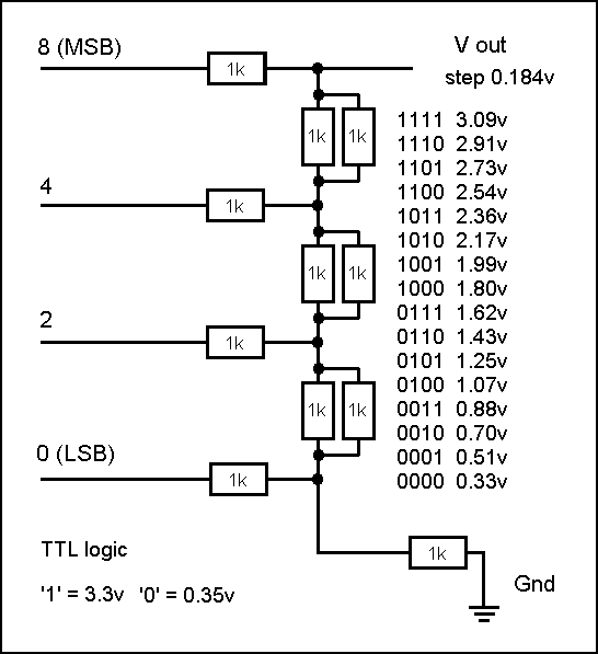
The simple R-2R binary DAC
One deficiency of the low-end PIC's is the lack of any Digital to Analogue (DAC) output (or Pulse Width Modulation - PWM) allowing simple servo motor control) circuit. Fortunately, a handful of resistors can convert 5 or 6 'binary' bits into a stepped control voltage forming a simple DAC

The 'easy' way to build a DAC is to use the classic R-2R resistor 'chain'.
The chain consists of a series of resistors 'R', with each bit is connected to the chain via double that resistance (2R).
So long as the drive pins output 'the same' voltages (and are capable of delivering 'reasonable' current') this will yield a binary weighted output voltage at the 'top' of the chain (assuming zero current is drawn from the top of the chain, i.e. the top is fed to an 'infinite impedance', like the input to an Op Amp)
For more on designing your own DAC, expand the note below
(+) D to A conversion - (R2R DAC)
Ternary (or 'trinary') logic
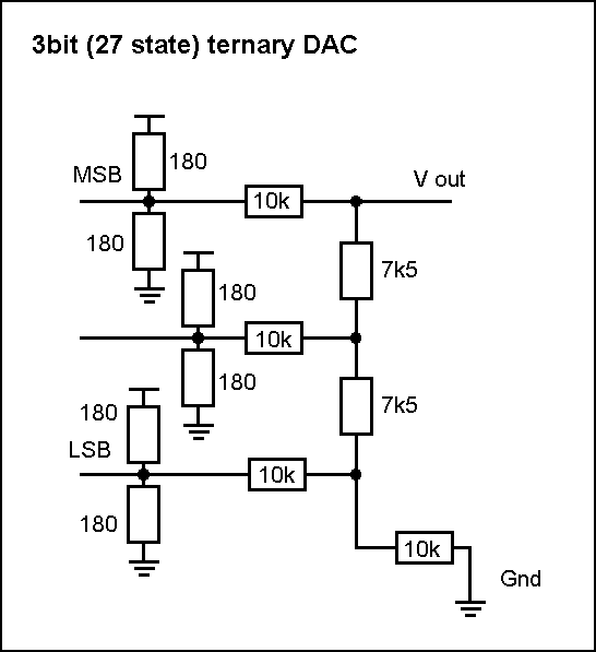
Using 'n' pins, binary gets you 2^n states, ternary 3^n. This makes a real difference to the number of pins needed very quickly = 3 binary bits (2^3) is only 8 states, whist 3 ternary (3^3) is 27 ! To get a 64 state DAC we would need 6 binary bits, whilst 4 ternary bits (or 'tets') gives us 81 states and 5^3 = 243 ! All PIC's have i/o pins that can generate 3 states = these are '1' (typically 4.3v), '0' (typically 0v6) and 'off' (input mode = 'tri-state' i.e. 'no voltage')

When the PIC pin is used as an output, the divider resistors will dominate the current draw. If we want to keep within 20mA**, Rdivider = 5/.02 = 250 ohms, or nearest E24 (5%) = 270 ohms (although we are using 5% resistors that's the 'absolute value' accuracy - in any 'random' batch you should be able to find 2 resistors making a 'matched pair' (i.e. correct ratio) to within the accuracy of your multimeter (typ 4 digits i.e. .1%) and that's all we need).
**The PIC has both a pin limit (20/25mA) and a 'total PORT' limit (typically 100mA). So you can build a 5 pin DAC at 20mA per pin, but a 6 pin DAC means reducing the current from each to 100/6 = 16mA .. of course when driving (or sinking) 20mA the pin output voltage will won't be 4.3v (or .6v) !
Next we consider the resistor 'ladder'. For ternary, the ladder ratios need to be 3R/4R (rather than R/2R). Since the 'chain' resistors must be high enough to avoid impacting the 'divider' resistor effect, the 'obvious' choice is 75k and 100k.
For more on designing your own Ternary DAC, expand the note below
(+) Ternary DAC - (R3R)
(+) Hybrid ternary bit conversion - (code)
The Hybrid approach
From LTspice we discover that a 3 pin 'ternary' DAC (so 3x3x3 = 27 levels) 'works' well, however above this the 'half voltage' divider of a 4th ternary bit pin overwhelms the voltages of the 3 lower bits to such a degree that the final ouptut voltage 'steps' are 'reversed' when the 4th bit is switched 'off'.
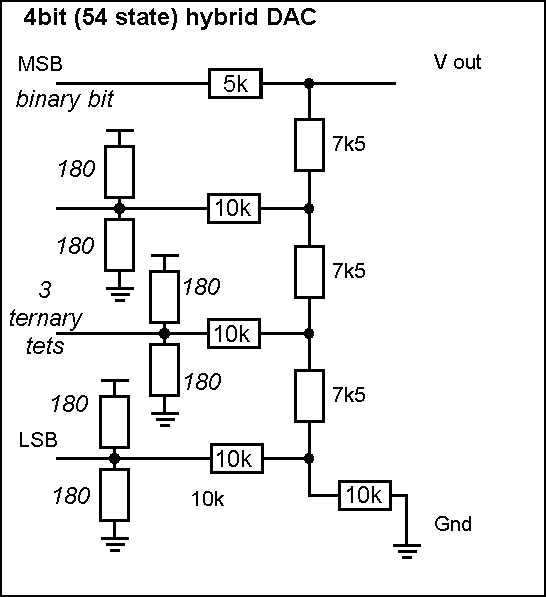
However we still want to get as many 'steps' as possible from the available i/o pins. So, how can we get over 50 steps with only 4 bits (and over 100 steps with only 5 pins) ?

The 'trick' is to run the 4th (and 5th) bit in 'binary' mode. 4 bits gets us 3x3x3x2 = 54 states whilst 4 binary bits is only 16 states (and 5 pins can deliver 3x3x3x2x2 = 108 states) ! To get anywhere near this, we would need 7 binary bits (which delivers 127 levels), whilst a 'pure binary' 5 bits would only deliver 32 states !
Using 180R for the 'half step' (2v5) divider resisters means each PIC pin sources or sinks 10mA (at 0v6/4v3). Using 3 bits from an 8 bit PIC i/o port uses 30mA, but the 4th bit consumes less than 1mA. This leaves some 70mA (of the 100mA PORT total) to be divided amongst the remaining 4 bits (about 17mA for each). This will need to be taken into account when deciding what to use the other bits for
PWM
Modern servo motor control circuits are all driven by Pulse Width Modulation. However it's difficult to achieve both a high enough PWM frequency (20kHz is about the minimium) and a decent resolution using a low-end PIC with it's internal (or simple external R-C) 4MHz OSC.
Typically you will want better than 1% speed control.

This implies at least 100 'step' PWM mark-space ratio - and assuming you can achieve 1 CPU CLK control this means a 100 CLK cycle time = whihc inturn is only 10kHz PWM frequency (4MHz OSC = 1MHz CLK, 1Mz/100 = 10kHz PWM)

The 'trick' is use a 50 step PWM mark-space and obtain a 'half step' resolution by switch from one PWM to the next each alternative cycle (so, for example, switching from PWM step 24 to step 25 (in a 50 step system) gives you '24.5' (== step 49 in a 100 step system)