

If you already know all about the Raspberry Pi, just skip straight to my Raspberry Pi Photoframe or Raspberry Pi JukeBox projects
Raspberry Pi - the not-so-good bits
The Pi A/B hardware was rather poorly 'thought out' for both 'educational' & 'hobby' use, however most of the hardware shortcomings were eventually 'solved' or 'worked around' in one way or another. More of an issue was the 'closed source' nature of the GPU code, which was supplied as a 'binary blob' and fixed pin assignments = we had to wait until 2016 before it became even slightly possible to assign functions to the i/o pins (as can be done by any PIC programmer)
There are still some fundamental SoC limitations - such as the single USB port - that can't be 'worked around' very easily (or even at all). Finally, there is the 'biggie' - the lack of any GPU programming capability (no, it will never support CUDA) - that has really held back the Pi.
For the first 2 years, all access to the GPU was via a closed source binary 'blob'. So, instead of a providing a programmable and (potentially) powerful parallel processing engine (24 GFlops is claimed), the Pi GPU could only be used to play movies and games.

All your code had to run on the obsolete single core ARM v6 CPU running at less than 1 GHz (so less processing power than the chip in any half-modern 'smart' phone or tablet).

It was not until Feb 28 2014 that Broadcom released the VideoCore IV (Pi GPU) OpenGL source code for OpenGL ES 1.1 and 2.0 plus driver stack for the VideoCore® IV along with the register definitions, although a 'binary blob' still exists for MPEG/h.264 (for Licence/DRM reasons), however it's a typical case of 'too little too late'.

During those '2 lost years', the 'average' programmer (and that includes high school kids) has been lured to the money making opportunities of the Tablet 'App' and the 'power programmer' to CUDA.

So whilst the project building hobbyist is happy that (some) GPIO pins can be reprogrammed to other functions, it's unlikely we will ever see much (if any) Open Source 'parallel processing' code running on the Pi GPU = especially as the most obvious applications would be video related which is still 'blob locked' (although you can play with GPU drawn OpenGL ES graphics for more information, see here)
On a more positive note, successive hardware releases have gradually improved the 'power' of the Pi, to the point where (with the B3) we now have a Pi 'on par' with any current generation 'low end' tablet, with 1Gb RAM, a quad-core 64bit 1.2GHz ARMv8 CPU and a built-in hub (with 4x USB, Ethernet, wireless and Bluetooth) for about £30 (and, as of mid 2016, it even runs Open GL 2.1 !)
Of much more significance is the Pi Zero. Although released in Nov 2015 is only became generally available in July 2016 and even then it was still being sold on a restricted 'one per customer' basis.

However by mid 2016 the Pi Zero had been upgraded to support the camera (CSI) socket and, for almost all projects the Zero replaces every other Pi (except the B3) with the sole exception of those needing the display (DSI) socket.

It small size makes it much easier to incorporate into a project that any other Pi (as does the ability to solder your 'power in' wires direct to the GPIO header 'holes') and whilst the Zero uses the same ARM v6 CPU as the original Pi's, it runs this at 1GHz by default (the original A/A+/B/B+ defaulted to 700MHz) and has 512Mb RAM (same as A+/B/B+).

More than anything else, it's the Pi Zero price (£4 'headline', £6.50 real world purchase = but still 1/3rd the price of the A+) that means it will be used in every new DIY project that needs any sort of computing power at all.

Indeed, the Pi Zero is so revolutionary that I dedicate a whole page to it.
One stated intent of the Pi Foundation was to keep the additional costs down, for both 'educational' use and for '3rd world' use. This was supposed to be achieved by allowing the use of 'old and existing computer parts'. See below for how well (or not) they addressed this goal
When the Pi Zero W was released in 2017, the Pi Foundation once again suggested that their main 'target' was 'children'. Plainly they are unaware of modern concerns about Health and Safety (yes, I can just see the average school allowing kids to play with a 250 degree soldering irons whilst they breath in lead/flux fumes ..)
Keyboard/mouse
The only 'direct connection'** supported is USB .... but to support the 'old' style keyboard/mouse, a 'PS2' connection would be required !
Since the designers must have known that most people would still have an old PS2 Keyboard and mouse 'around the house' (even if hidden in the attic), I can only assume that IBM demanded a Licence fee for the socket 'copyright' (PS2 is a very simple low speed 'serial' connection, and the SoC has many 'spare' i/o pins that could have done the job ..)

If you shop around, you can get a cheap USB keyboard+mouse for about £10, but that's still more than half the cost of a Pi A/A+.

Given how unreliable direct USB connection proved to be (see below), I give them '0/10' for (not) allowing use of real 'old' keyboard/mouse (although a "PS/2 Keyboard+Mouse USB adapter", dual PS/2 sockets to a single USB plug can be had for £1, even from Amazon (or you pay £5 to get the same from a 'Pi shop' :-( )
Unless you are using using a dual PS/2 to a single USB plug (with PS/2 KB and mouse), you will need 2 USB connections (one for each of your USB keyboard & USB mouse). Suddenly we are looking at even more cost on the A/A+ (i.e. the need for a USB hub) or using both USB sockets on the B
However, on the model B series, you don't actually need to use any of the USB ports for KB/Mouse as the Pi can be controlled from a 'Terminal Window' on a PC, via the Ethernet connection.
On the B, due to USB/Network contention issues (see later), a directly connected Keyboard / Mouse can (does) suffer from 'jitter' (missed and repeated keys, jumping mouse cursor etc) any time you use the Ethernet (or any other USB device).

The A, with it's single USB connection, does not suffer from this
**Whilst there is no PS2 socket, there IS a serial link 'console' (on pins 8 and 10), however few PC's have RS232 ports anymore (those that do are typically laptops and laptop TxD will be 0-5v whilst the Pi RxD is a 0-3v3 input (a simple resistor level converter will do the job)). The PuTTY utility can then be used to control the Pi from your PC
One other 'user control input' is provided = the HDMI 'CEC'** protocol over a bi-directional HDMI cable.
**HDMI CEC is also known as Easylink, Vierra Link, BRAVIA Sync, Anynet+, etc.
This allows the Pi to be used as a sort of 'multi-media' system (as it is capable of 'understanding' the 'TV remote control' button pushes).
Today we have one final choice that allows a user to control the Pi = the 'touch screen' display panel connected to the DSI option socket (see below)
This option was not available at 'launch' = it took about 3 years before the display became available.

The typical cost is about £50 (although 'Chinese Copies' can be found for less) which means this is not a viable option for 'poor 3rd world schools' (such as those in UK)
Display
The Pi will drive either digital (HDMI) or analogue (composite Video, via a RCA jack, intended for the ancient CRT 4:3 TV (but ideal for using the Pi as a CCTV camera = see below)
(+) Using the RCA socket
The Pi does not support 'older' computer monitors at all. These all use the 15pin analogue VGA connector - although if your 'old' computer display is slightly more modern it may (also) have a digital DVI socket allowing you to use a simple HDMI to DVI adapter.
When the Pi was being designed, during the 4 years prior to it's initial release in Feb 2012, the SVGA socket was 'common' and HDMI the 'brand new' connection. Indeed, at that time computer displays where moving to DVI, not HDMI at all.

So the lack of SVGA is apparently down to Broadcom (the display is driven by their closed code) as there are plenty of I/O pins that could carry the necessary 8bit RGB, although it's also possible that the expectation was that 'most' users would press into use an old analogue TV display (see note re: default display below)

Enterprising users have since worked out how to get the GPIO to drive VGA video out using about 20 of the GPIO pins on a Pi B2 (3x6 bits ea. rgb, 2x sync) with minimal CPU overhead (i.e. driven by the SOC), which proves it can be done (and gives the lie to those who claimed otherwise)
By default, the analogue RCA display would be used (the Pi Operating Systems (Wheezy) would try to 'detect' the existence of your HDMI display at power on, and if not found they would default to the RCA analogue socket). Of course a HDMI to VGA 'converter' wouldn't be detected, which made supporting VGA even harder :-(
(+) Getting VGA from the HDMI socket
Fortunately the current (Jessie, 2016) build of the Operating System defaults to using HDMI on first boot
Whilst I agree that some 3rd world users might have access to ancient CRT TV's (and I guess CRTs might still exist in some of the UK's poorer schools), the vast majority of 'old monitors' will be 800x600 SVGA (or better)
So it's 1/10 for supporting ancient CRTs, plus 5 points as the RCA socket will be needed for CCTV applications (with the Pi Camera), but then -5 for failing to support 'old' SVGA monitors. Adding 5 for HDMI (but a '-' for the silly start-up default to RCA) gives a total score of 5/10 for display support, or C- 'could do better' :-)
Other display options
Those wanting a smaller display for the Pi should consider using a LCD panel intended for automotive use - these will run from a single 12v supply and have AV (composite video) inputs (so use the Pi RCA analogue output)

An even smaller and cheaper option (except for B3 Bluetooth users) is a serial controlled 2 line 16 character display. Many vendors (eg Amazon) offer the 'SparkFun' display at about £20-£25. For what must be the cheapest possible option, go to eBay and search for "Serial x2 LCD" (if you scroll down to the 'items from International sellers' you will discover the Hong Kong seller offerings at about £5)

Serial displays would use the 'serial command' port (see below, especially for B2 Bluetooth note)
(+) Using the Pi RS232 serial links
Power
Power connection is via a micro-USB connector, the declared 'intent' being to 'allow the use of old mobile phone chargers'. The problem with this is that 'old' mobile phones never had micro-USB = they all came with either mini-USB or some 'custom' connector !
The plain fact is that a 'bare' (i.e. unsupported by any case) PCB mounted micro-USB socket is totally unsuitable as a 'multi-use' power connection anyway. It is literally a disaster waiting to happen - after only a few dozen inserts/removals the socket housing is so deformed that the power cable will just fall out under it's own weight.
The decision to offer micro-USB 'only' thus seems perverse = at the very least they could have provided extra 'lands' (at zero cost) near the edge of the PCB, near the 'power input' plug position, so that the hobbyist could at least solder on a standard 'barrel' type connector. Better would have been a couple of holes to allow +5v / Gnd wires to be soldered direct to the PCB (we had to wait for the Pi Zero for this).
My experience with the Pi is that a loose power socket is one of the main causes of Pi 'random resets'. After only a few dozen uses the power connection becomes intermittent - soon the only way to stop the power plug just falling out under it's own weight is to add elastic bands to keep it in !

In fact, it seems some users have become so aggressive with the power plug that they ended up breaking off the socket (this is not just a Pi problem = modern tablets and smart phones use the same socket and, despite the added mechanical support of their plastic cases, suffer from the same breaking off ...).
In short, the micro-USB socket is totally unsuitable for any sort of frequent or long term usage - and what really kills it is the lack of any 'Reset' or any sort of separate 'power off' switch on the Pi, so frequent use is inevitable !
The next issue is the power required = you ideally need a '5.2 volt' supply that is rated to at least 1A
The actual Pi consumption is quite low** - the 'A' < 200mA, the B < 450mA, whilst the B+ is about 250mA = see Mikronauts.com , however a power block rated at less than 1A is typically unable to cope with the 'transient' power spikes demanded by the Pi - especially when hot-plugging a USB device - and the resulting voltage 'droops' will lead to the usual random Pi reboots
** Although, much to the annoyance of the battery based hobby user, is the fact that the 'sleep' (or software 'off') power consumption is not much lower.

If you expect this to be 'near zero' you are in for a shock - the Pi has no control over the power supplied to USB plug-in devices (as noted below, the incoming +5v is wired, via a reverse protection diode, 'direct' to the USB +5v), so whilst the CPU may be 'sleeping' the USB devices will still be fully powered up !

Even the Pi alone consumes power in 'sleep' mode = the Model A typically 30mA and the Model B a whopping 125mA (although with the B+ that does drop to 70mA)
Whilst modern phone chargers are indeed all micro-USB, modern phones use a lot less power, so the chances of finding 'an old modern phone charger' at anything over 500mA, let alone the 1A you need, are effectively zero.
In fact, the only 'old phone charger' that's going to 'do the job' would be those for the first generation of 'smart phones' (eg Blackberry, HTC) or for a early 'tablet' computer, such as the power adapter intended for the Kindle (but make sure it's not one of the very early 0.85A 4.9v ones). Few of these are likely to be found 'sitting around' waiting to be re-used in schools.

This, however, is not the end of the power issue. Whilst the Pi's main chip runs on 3.3v and the Pi has 3 'on-board' regulators (3.3v, 2.5v and 1.8v), the one thing that really does require 5v are the USB outputs - which means you really do need to supply 5.2v (but not more since the 'over voltage protection' (a Zener diode) will 'cut in' to limit the on-board voltage to 5v !) especially if you intend to plug in just about anything to the USB except a keyboard/mouse (see USB issues later).

Of course if you don't need USB (or only ever use a self powered USB hub) you can 'get away with' a 4.8v (or even lower) supply.
Even if you manage to find 'an old old phone charger' that can supply sufficient current at no less than 5.0v, it will inevitably come with either a mini-USB or (more typically) some sort of 'proprietary' plug.
Those with a suitable 'old' charger may find a 'mini-USB to micro-USB' adapter on eBay for 99p - however if you are using a charger with a proprietary plug (that has to be cut off) you have no choice but to solder the wires directly to the Pi (as micro-USB cable plugs with 'solder tags' didn't exist in 2012, although you can now purchase a micro-USB 'insert' adapter designed to fit inside a standard USB socket device and to which it would be possible to solder wires).

Of course this is a bit of a pain - as already mentioned, there are no 'lands' intended for direct soldering of incoming power (the exception is the Pi Zero, where you can wire you incoming power direct to the 0.1" header)

The +5v can go to the underside of the board and be soldered to the tab of F3 near the edge of the PCB, whilst the Gnd can go to the C6 pad also near the PCB edge (so, if you are careful, it might even be possible to solder a micro-round pin power socket to these pads).

There are two other alternative ways of 'connecting' power direct to the PCB, however both these approaches will bypass the input 'poly-fuse' (which is the cause of many voltage drop issues, see later, so bypassing it may actually be a 'good idea' :-)

The first is to use the 'TP' (voltage Test Points), the second the 'GPIO header' (+5v is on the pin at the corner of the PCB, GND is the 3rd pin down from that)

The final approach is my preferred one - treat the Pi itself as a 'USB device' and power it from a powered USB Hub ! This means you have to 'back drive' the Pi via the USB 'input' cable (see later)
[Note that the B+ has a 2A input fuse followed by a DMG2305UX (a clever semiconductor based 'reverse protection' device - for an explanation, see here) which 'drops' less than 0.1v at 2A (a normal diode wold 'drip' a lot more).
Whilst this still means that the incoming '5v' may still be somewhat less than 4.9v before being 'fed' to the USB sockets, the new AP2331 switching regulator (apparently) solves the 'drop out' (reboot) issues caused by voltage drops due to plugging in USB devices. The new regulator (apparently) also eliminates the 'hum and hiss' that plagued analogue audio output.]
Avoid the type of power block with a USB 'socket'. Whilst it's easy enough to connect to the Pi with a USB to micro-USB cable, the USB cable plug can be a loose fit to the power supply socket, with the result that the Pi will 'reset' itself at random intervals
UK mains plug adapters
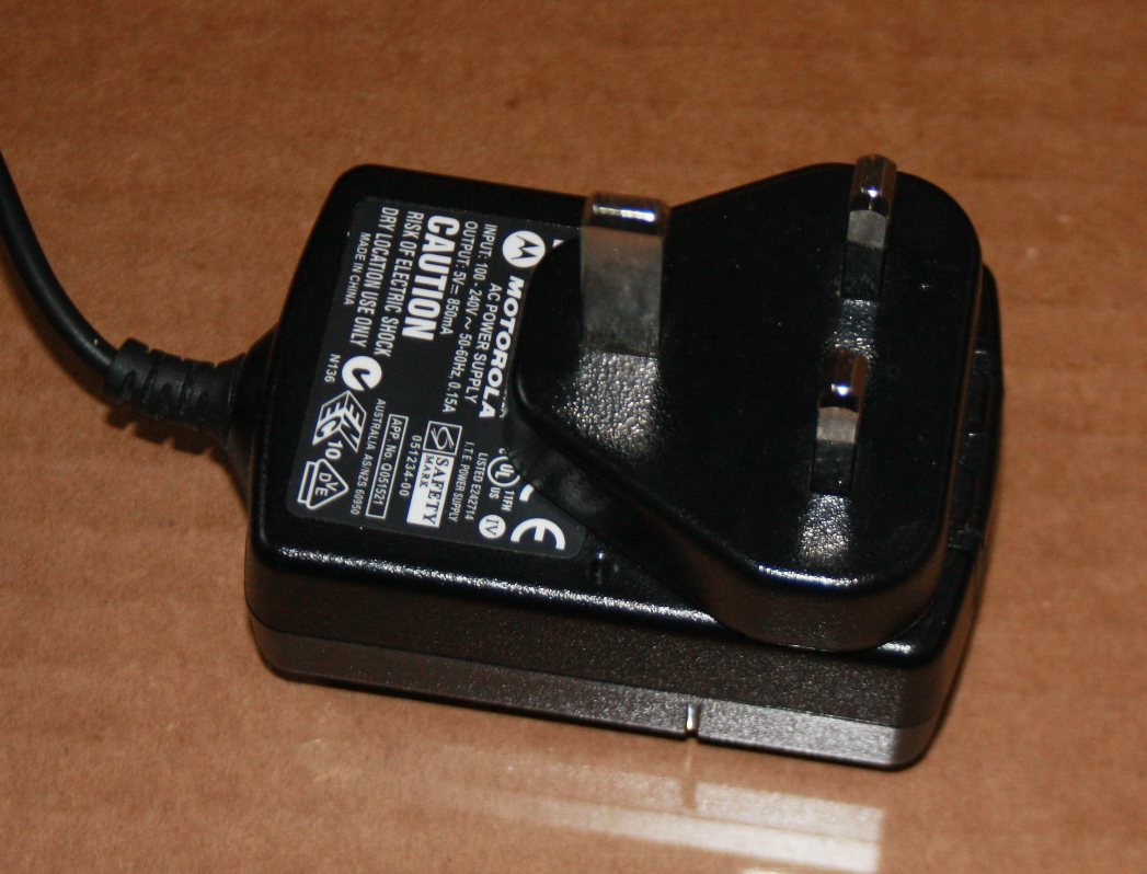
 Of course UK power adapters incorporate a UK mains plug and are designed to plug into a UK mains socket - and having to use something equipped with the huge UK mains plug & socket is a real pain - although it is possible to find a 'universal' phone charger designed to be fitted with a separate 'national power plug'
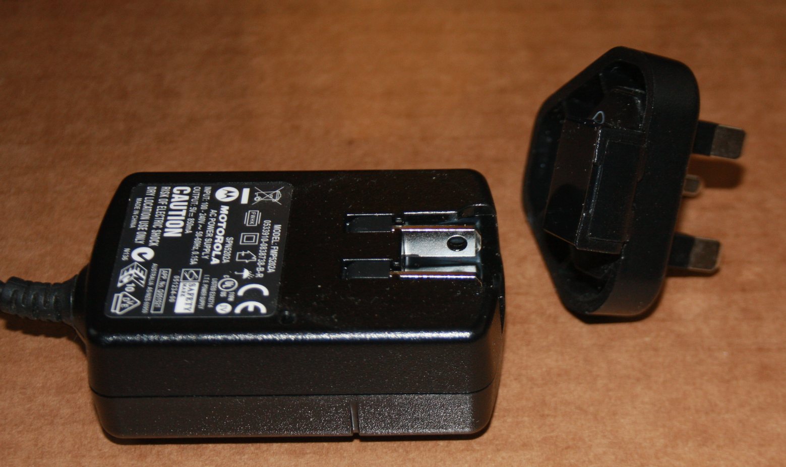
Others can be found, however check if they are equipped with a micro-USB connector (the Motorola one shown above has a mini-USB plug NOT micro-USB - further, although it's 'rated' at 850mA, in practice it could not even manage 4.8v at the current needed to drive a model A Pi (I know, I tried :-( ).
'Universal' or 'International' adapters typically have flat 'fold away' US style power pins into which a UK (or other national) mains plug is 'clipped' - others have 'clip on' studs. Removing the UK mains plug reduces the size to 'something reasonable' (30mm or less) and allows a mains cable to be soldered directly to the pins (thus eliminating the need for a massive UK power socket)
Most Blackberry/HTC chargers (approx cost £10 bay - although Amazon has started selling the first class 2A Blackberry charger at less than £4 !) are of that type.
If your adapter has fixed UK power plug pins, and you need to get the height down, you can (of course) chop them off and solder a mains cable directly to the 'stumps' !
Those wanting to build a project using the Pi and position it somewhere without an electrical mains power extension (eg. a remote camera for bird-box / wildlife observation - or a home CCTV system) should read on ....
Power Over Ethernet (PoE)
Given both the size and low power consumption of the Pi, PoE is an obvious consideration for the hobbyist. However this was plainly never even considered
Instead the Pi's designers have chosen an Ethernet socket with internal circuitry that shorts pin 4 to 5 and pin 7 to 8 (so far so good) but then feeds them via some sort of internal resistor / capacitor circuit into the 10/100 receiver transfer circuit (see page 3 of the Pi circuit diagram).

This means that the pins used for PoE (4,5 and 7,8) have to be 'split off' from the incoming Ethernet i.e. you have to cut open the cable (or use an adapter) to 'split out' the power pairs (4/5 & 7/8) to prevent them reaching the Pi's Ethernet socket (otherwise any 'noise' on the 'power lines' will be fed straight into the Ethernet receiver / transmitter)

For more on PoE, see below :-
(+) Power over Ethernet - (PoE)
The USB port(s)
The plain fact is, the Pi's USB ports are not compliant with the USB power standard (see below). Worse, from a through-put point of view, is that the SOC only has a single USB port (the B,B+,B2 and B3 all have an on-board Ethernet+USB hub chip)
On the Model A/A+ and Zero the SOC drives the single USB socket 'direct'. On the model B, the SOC port is wired to an on-board LAN9512 chip (it has 3 ports = dual USB + an Ethernet), whilst the B+/B2 uses the LAN9514 chip (5 port = 4 USB + Ethernet).

All USB i/o is driven (by software, byte at a time) via the SOC i/o 'bus' which has a theoretical limit of 60 Mbytes/s (480 Mbits/s). A single USB 2.0 port running at maximum throughput (280 Mbits/s) would consume over half (36 Mbytes/s) of this, although 'real world' tests on the Model A (with it's single USB port) shows that the actual max. data rate supported is closer to 30 Mbytes/s (240 Mbits/s) - which implies at least 10% software overhead in handling USB data.

In fact when you start to use multiple USB devices with real data, it turns out that the USB rate is CPU limited - i.e. at max. USB, the CPU is 100% loaded (so 'overclocking' the CPU will actually increase the USB data rate !)

It is not even theoretically possible to run 2 USB's (let alone 4) as well as a 100mbs Ethernet (on the B's) at 'full speed' (real world tests suggest that the maximum you will get out of the '100mbs' Ethernet is about 30mbs). If you try, the 'multiplexing' required can (and does) lead to 'data loss'

Fortunately, Ethernet is (relatively) immune to data loss (since packets have to be 'acknowledged' and 'retransmit on error' is 'automatic') as are USB connected disk drives (which do work, but must have their own power supply - although on the B+/B2, you can 'get away' with powering a 2.5" hard drive via USB if the B+/B2 has a decent enough power supply).

Thus, in practice, the only 'common' devices to suffer from 'lost' data are directly connected USB keyboard / mice !

Of course there are also some USB devices are unable to cope with any sort of 'pause' caused by a 're-transmit' or 'interruption' to a smooth data stream = most USB audio devices, for example (of which more later)..
Despite the Ethernet/USB 'bottleneck', the Pi can play HD movies direct from a USB connected device (even a BD drive only needs 30 Mbits/s for HD) and has been successfully used as both a DLNA 'client' ('rendering' movies received on it's Ethernet port to it's HDMI output) and even as a 'DLNA Server' (streaming HD movies from a USB connected device to it's Ethernet port). This is can be achieved because the GPU is handling all the complex h264 decoding etc. allowing the ARM CPU core to dedicate itself to nothing but actual data i/o.
Note that playing audio / video off the SDHC card is also possible. Even the low end 'class 4' (4 Mbytes/s) device can deliver a maximum of 32 Mbits/s, which is just within the 30mbs required to support full HD.

Note also that the Pi will support class 10 SDHC cards, some of which have been measured to run at almost 20 Mbytes/s (160 Mbits/s) with minimal CPU overhead. In fact, if you are actually processing something (eg video, from the Pi camera) and need to 'save' results at high speed, the SDHC card is the only place (other than the very limited RAM) where it can go (for sure it's going to be faster than USB/Ethernet)

It's to be noted that newer versions of the Pi system software ('NOOBS') make use of the SDHC card as 'virtual memory' (essentially the same as MS Windows with it's 'swap file')
Power to the USB sockets
It is plainly impossible to deliver 5.0v to the USB output sockets from a 5.0v input when the path from the Pi power input to the USB output was designed with 2 'poly-fuses' and a reverse protection diode 'in the way'.
Typically the USB ports would get 4.75v (or less), which means about the only devices that would work are USB Keyboards and Mice (at a guess, the designers never considered any other use for the USB ports)

The polyfuse for each USB socket (F1, F2, replaced from August 25 2012 with wire links) was only rated at 140mA, whilst the 'reverse protection' diodes (still in place) are rated at 200mA.

This means that power supplied to the USB sockets is not even half that required to achieve 'USB standard compliance' (the USB definition requires USB sockets to deliver at least '5 unit loads' i.e. 500mA)
Whilst most users now use 5.2v 'chargers', a device plugged into a Pi USB socket can still get less than 4.8v at 200mA (and will blow the diode if it tries to take more)
USB 'hot plugging' issues
As the typical phone / tablet charger power-supply (and Pi input poly-fuse) 'resists' any sudden increase in current, when a device is plugged into a USB socket the on-board voltage can drop well below 4.75v as the device 'powers-up', with the result that the Pi will typically 'crash' (reboot)
Solutions to the USB 'hot plug' problem are :-

(1) Use a 'better' power supply - those rated at 1.5A and above are typically be able to supply enough 'instantaneous' current to avoid the voltage dropping to the 'reboot' level (note, however, that the Pi's input poly-fuse will 'resist' (act against) sudden current surges)

(2) fit a separate powered hub between the Pi and any USB device (the recommended solution)

(3) beef-up the Pi's on-board ability to deliver sudden current surges - replace the input capacitor (C6, next to the micro-usb power connector) with a 1,000uF electrolytic capacitor (rated at least 6v) AND add a "low ESR" capacitor of 100uF (or more) rated at 6v across the USB socket power output pins (i.e. in parallel with C32).

Note - for my Pi photoframe a script was used to look for photo's on a USB stick each time it 'started-up'. So having the Pi 'crash' (restart itself) when a new USB stick is inserted was actually an 'advantage' :-)

Needless to say, I ended up with such a good power supply that the Pi refused to 'crash' ! To solve this, I had to fit a Reset switch (and mark it 'Load from USB' :-) ).

WARNING - if you are running an application that 'saves' to the SDHC, the Pi could actually be writing to the SDHC card when it is 'hard reset' and you then risk corrupting the SDHC - in that case, wire your 'reset' switch to a GPIO pin instead of the 'Reset' pin (and have the Pi software reset itself).

Note that with the B+ and later, a dedicated Hot-plug voltage generator chip sits between the Pi power in and the USB sockets (so the B+/A+/B2 (and Zero ?) should not suffer from 'drop-outs').
Choosing your USB Ethernet dongle
As with all add-on USB 'dongles' for the Pi, you need to chose one that has DRIVERS that will work with the Pi. This means sticking to the list of peripherals known to work with the Pi. No matter what the 'brand name', most will be made in China. However, as you will see from this list, there are a lot of problems with 'Chinese copies' of 'brand name' devices that may look the same but incorporate different (presumably cheaper) chip-sets. I suggest you buy from CPC, Amazon etc. rather than eBay (yes, even Amazon gets 'caught out' occasionally but at least you can send a non-working one straight back).
Audio
Audio output is either analogue stereo (via a standard 'headphone' 3.5mm jack socket (which connects via the analogue video socket on the B+) or digital 'surround sound' (via the HDMI connector, which is 'DRM protected' by closed source GPU code).
Unlike almost every computer these days there is no way to output decoded 5.1 digital as 6 channel PCM output (usually via 3 x stereo sockets), so there is no way to drive a 'standard' computer 5.1 speaker set
In theory you could use 6 of the GOP i/o pins to output the required data steams = you 'only' need a binary (on/off) bit stream (so there's no fancy 'PWM' or filtering to ruin the data) - and at 48kHz with 16bit samples, that's only 768kbps per channel.
Of course you can't use the 'closed source' GPU to do the 5.1 AC-3 / AAC / DTS to PCM decoding, however the ARM CPU is 'just about' up to the job (and this type of decode is supported in 'omxplayer' and 'xbmc'). The challenge is, of course, to divert the decoded data steams to your 6 chosen i/o pins (rather than have it sent to the GPU / HDMI socket)
On the B+, the SOC PWM is still used to generate the audio output - but now the PWM power supply pin is tracked to a dedicated power supply rail, which means it's completely clear of digital feed through. Apparently there is also a 'dedicated output driver' (i.e. the closed source GPU code has, at last, been fixed although it remains to be seen if this also improves existing A & B board audio).
Stereo output (3.5mm jack)
The analogue stereo jack output on the A/B is driven from a software controlled PWM running at around 40MHz, which is then low-pass-filtered & capacitively decoupled to the 3.5mm jack socket. The result is equivalent to a 'low resolution' D-A converter of 10 (or perhaps 11) bits at most.
Further, it has a relatively high output impedance, so insufficient current to drive almost any modern 'Hi Fi' headphones direct, although on the B+ (and later) this was addressed by changing the DC blocking caps to 47uF (which makes 32-ohm headphones usable in terms of bass response and volume)

Even so, the 3.5mm jack output quality will never be 'Hi-Fi' (and any attempt to output Dolby ProLogic II via this path is doomed to fail as the D-A and low-pass filtering trash the data)
Because the output is essentially fed directly by software (aplay etc), almost anything can (and does) upset the audio data 'stream'. Indeed, some users report that 'high data rate' mp3's (above 128 kbs) are unplayable as the software decoding can not keep up with the data feed required (instead use 'mpg321' to pre-decode the .mp3 to a PWM .wav file and then use 'aplay' to 'play' the .wav file)
If you run into a 'can't keep up' problem, try 'over clocking' the ARM CPU
There were all sorts of audio problems on first release.
For example, if the software driver releases the GPU i/o pin (at the end of a music track), the Broadcom firmware sets the output 'Lo' (0v) discharging the decoupling capacitor (and causing a 'pop').

Of course, when the next track is started, the pin is driven 'hi' which results in a pulse of about 1.65v at the jack socket - this causes a massive 'crack' (the standard i/p of amplifiers is rated to 1v max, so if your amp. is set a high volume, a 1.65v pulse could literally blow your speakers away :-))

To eliminate the start up crack, a firmware change was made in Feb 2013 to start the PWM at 0% duty cycle and gradually ramp it up to 50%. However it seems that this change only worked when using 'aplay', and then only if the audio being played was 48kHz, 16bit signed little-endian. Other audio formats still started with a loud 'crack' as did other software (such as 'omxplayer', which gave three 'clicks' when starting to play a track via the analogue o/p).

A further fix was implemented in March 2013, so the GPU firmware does not 'turn off' the pin at all (just do "sudo rpi-update" to get the latest micro-code). The first track played after power-on still starts with a 'crack', however there are no start (or end) pops, clicks or cracks after that.

An alternative 'work-around' to the audio problem was to set the MPD audio player to use 'PulseAudio' (which could also be set to never let the audio Hardware 'go to sleep'). This prevented 'clicks' at both the start and end of tracks but also meant that the Pi was 'always' playing audio (as well as leading to problems if you 'paused' the playback)

All this 'fumbling around' suggests that the original design was never correctly thought out, nor was the hardware fully tested (if it had been, the 1.6v 'crack' would have been discovered before shipment)
Whilst the pops, clicks and cracks caused by the sudden GPU i/o pin voltage swings are now 'fixed', many users still complain of hum and hiss from the stereo output during normal audio playback
In most cases, this is actually being 'caused' by the power-supply - a phone charger that was never designed to support sudden changes in load nor to supply perfectly 'clean' power. As a result, 'hum' can 'leak in' and, as soon as any USB device starts operating, the 'instantaneous' voltage can wander about 'all over the place'.

So isolating the USB devices (by using a powered hub and removing the 5v power at the Pi USB socket to prevent any possibility of the Pi driving a USB device) can make a real difference to stereo 'audio out' quality !

The 'B+' revision (July 2014) has improved on-board voltage regulators and a dedicated 'stereo out' voltage regulator. These changes are understood to have finally put paid to the 'hum & hiss' complaints

None of these fixes address the fundamental issue of the analogue audio output = the fact that using a PWM circuit delivers audio quality equivalent to about 6 to 7 bits per channel (rather than the 16 bits present in a WAV track)
HDMI audio
The HDMI output is driven by the closed source GPU core code. I believe that only AC3 or DTS audio are supported, and then only if you specifically select 'pass through' to HDMI (i.e everything else is down-mixed to 2Ch PCM stereo before being output to HDMI).

Unfortunately, due to DRM (Digital Rights Management) restrictions on the GPU core code, it is (currently) impossible to 'divert' (or copy) the digital surround sound audio away from the HDMI output to some other i/o pins  = so those thinking of fitting SPDIF to the i/o pins (to get 5.1 audio) will be disappointed (but see USB Audio, later).
If you don't have a home movie system with HDMI input, you can still get 'high quality'** stereo audio from the HDMI by using a HDMI to VGA Converter with audio 'split-off'. Note that these deliver analogue stereo (so anyone expecting 2 channel PCM Dolby Prologic II encoded 5.1 is going to be disappointed). The cost is still about £20, although the price has started to drop recently (mid 2013)
**Don't assume that HDMI is immune from audio issues. The audio quality from the HDMI output is very much a function of the software - audio distortion during h264 HD video playback is/was a real issue with 'omxplayer' where-as the 'XBMC' software always coped OK.

Note that: many of the cheaper 'HDMI to VGA' devices will NOT support 'arbitrary' display resolutions - sometimes the (Chinese) suppliers will state 'not support 1280x800' (which will provide a hint of resolution restrictions), sometimes not. Especially note that many HDMI to VGA 'converters' do not support older '4:3' 800x600 VGA monitors from 16x9 feed (of course, after boot-up, you can get the Pi to send whatever resolutions you like, including 800x600, down the HDMI line).

Note also: many HDMI converters with 'Audio out' are 'advertised' as 'Pi compatible' BUT they will draw well over the Pi's HDMI reverse protection diode limit (D2, 200mA) ! There have been reports of blown diodes and even 'burnt' HDMI PCB tracks. Check the device power requirements (or get one with a separate power option, or one that can be taken apart and modified). Often ones with 'external' power option come with a USB lead - so you need to check the rating against the Pi's USB power out limitations :-)

See the list of Pi tested HDMI to VGA converters

Finally, be aware that what you get out of almost 100% of all 'HDMI audio converters' is 2 channel stereo (this even applies to those with S/PDIF sockets unless specifically stated as 'supporting AC3 pass-through')
USB Audio
Apparently, you can get the ARM CPU to send digital (PCM) stereo out via the USB port, which implies at least Dolby Prologic II support (if the ARM software supports that). Needless to say, any other 'activity' on the USB ports at the same time as audio playback can 'upset' the data stream :-(

The May 2013 update to USB drivers solved many of the USB sound problems (pops & crackles during other USB use), however apparently there are still some data rate 'smoothness' problems
The data rate issues may never be fixed. The plain fact is that the Pi has a single USB 'port' on the SoC and this has to be used for 'everything' (the B/B+/B2/B3 etc. with multiple USB / Ethernet etc. ports simply have an on-board USB hub - everything is still bottlenecked down a single port on the SoC). When you use 'multiple' USB devices, data 'drops-outs' can and do occur. Whilst Ethernet, disk i/o etc. can all cope with variable data rates and re-transmission on collision/error, when it comes to USB audio every 'drop out' is an audible 'hick-up' in the smooth music playback
Further there is a quality issue. The only real solution for those wanting to use the Pi as a CD quality stereo 'music system' is to output via a 'class compliant' USB Audio device (such as the Creative Soundblaster Play). Even on eBay, USB audio devices are quite expensive (approx £20) and any that require a Windows/Mac driver will not be 'class compliant' (so won't be usable unless you write your own Linux device driver :-) ). Even so, it should be possible to build a CD ripper / store / player with similar functionality to the Vortexbox NAS Appliance for less than 1/3rd the price !
An audio CD holds 16 bits per channel at 44100kHz, giving a data rate of (16x2x44100 =) 1.4 Mbs (Megabits per second). USB 2 supports an effective throughput of 280 Mbs, so there should be no problem both reading from a CD and writing to a audio output device.

However, all i/o has to share the same 'path' on & off the GPU chip and this can lead to 'skips' and 'jitters' as the overhead of 'serving' one device / path impacts the 'smoothness' of data transfer on all the others.
In theory it should be possible to get 5.1 via USB, either as 2 CH PCM (DPLII encoded 5.1) or as 6 CH PCM (suitable for direct drive of a computer 5.1 speaker set). However, despite wading through mountains of junk '3D sound' audio 'gaming' USB to headphone adapters, I've not managed to find a USB to 2CH PCM adapter, let alone a USB 5.1 to 6 channel PCM ...
For more on setting up the 'ALSA' software to 'drive' 5.1, see the ALSA wiki pages
The I2C/I2S solution
I believe the the only real solution to getting Hi-Fi quality smooth analogue audio playback is to 'divorce' the audio data stream from the USB bottleneck
To do this, you will need to plug in a DAC to the GPIO header (see, for example, the 'HiFi Berry DAC+' (approx £25) = or, better, the 'pHAT DAC' (cost about £12 and intended for the Pi Zero, but will work just fine with all the other Pis)
RAM memory
The memory is fixed ('bonded' to the top of the ARM/GPU chip package), with no possibility of expansion. The model A/A+ has 256Mb, the B/B+/Zero has 512Mb and the B2/3 has 1Gb.
A better choice might have been to fit one or (better) two laptop memory SODIMM type 'sockets' thus allowing the re-use old laptop RAM SoDIMMs.

This could have allowed users to fit additional RAM (the ARM core limit is 4Gb, however the 'video core' (GPU) has a 1Gb limit, so in practice, the limit is 1Gb)
In practice, 512Mb is plenty for almost anything you might want to do, although 256Mb is a bit tight if you run any sort of GUI. Whilst the GPU shares RAM between program and display 'dynamically' (it can allocate up to 256Mb for HD display animation, so don't try playing full HDMI resolution games on the Model A/A+ :-) )
The Raspbian Operating System core is quite 'small' (the 'Wheezy' core code itself runs in about 16Mb of RAM) and (so far) no-one has ever complained that they can't fit their applications within the available RAM. However with the advent of the Pi camera this is going to change. In still picture mode you can get 15 frames per second and 5m Pixels LUV is 7.5mb/frame. This generates 112.5Mb/s and the only place it can go is into RAM, so you only have room for a second or two before running out of RAM (even offloading to a Class10 SDHC at 20Mb/s will not solve the problem).
Note that the GPU firmware 'controls' access to the RAM. Early users had problems moving their SD card from the Model A to the B (since the code would refuse to 'see' the 'extra' RAM) or from B to A (as the system immediately crashed when 'half the RAM' was found to be 'missing') - however these issues have now (mid 2013) been addressed (if you have problems moving your old SDHC card from one model to the other, it is only necessary to do a 'sudo rpi-update', to get the latest GPU micro-code, before moving the SD card)
Current Pi system software implements the Microsoft trick of using a 'swap file' to make the limited RAM go further (apparently no-one has warned the coders that SDHC cards have 'write lifetime limits').

On the other hand, Linux 'tmpfs' allows you to create a 'RAM Disk' at any 'path' (directory/folder) you choose and treat that as a 'normal' file system (so you can off-load your own applications continuous write requirements to RAM).
SDHC
The Pi really needs at least a 4Gb SD card - and these are not 'obsolete' - where-as CF cards are (almost). Further, the CF card 'interface' is essentially the same as the old IDE hard drive (which can be found in almost any old laptop and inside many 'USB' external drive enclosures).
However, it must be accepted that the GPU core was never designed to 'run' from any sort of 'boot disk' and to make it do so would likely require some sort of separate 'BIOS' chip be fitted (with a consequent increase in cost). So, whilst a direct connect CF / IDE (or even SATA) 'option' would be 'nice', this was always one huge leap too far for the Pi (but feel free to Google 'Banana Pi' if you really need SATA) :-)

It is to be noted that on the Model B+ the SOC pins designed to 'boot' from a serial 'BIOS' device have been 'exposed' on the new 40pin header. In theory this could allow the OS to be placed on some 'BIOS' chip (added by you) whilst the mini-SDHC socket on the B+ could be used for 'removable' devices
SD cards have a 'write lifetime limit', however these are high enough to be ignored when writing files (SDHC cards are typically specified to 1,000,000 writes) and the operating system has been configured to minimise writes (some 'journaling' file systems update the directory with 'last access times' every time any file is read and 'log' files are constantly being written - however it IS possible to disable almost all writes (and re-direct the rest to tmpfs) and thus set the SDHC to 'read only').
Those writing their own software that accesses the SD file system need to be a bit wary - a program 'loop' that makes continuous writes to the same location (eg to the directory) could well run into the SD 'write life time limit'. You might also run into 'write lifetime' limit problems when using the SDHC to 'save' photos from the Pi camera - for example, in a 24x7 security CCTV type application
Whilst the Pi used to be very 'picky' about which make of SD card you used, it now accepts (almost) any. Tests have been done with SD cards up to 32Gb and (some) class 10 cards that can achieve almost 20 Mbytes/s !
Note. The A/B Pi only supports SD cards using the 3.3v interface standard. Most class 10 cards attempt to switch to 1.8v before running at their 'rated' 10Mbytes/s speed** = when ignored, many will 'revert' to half this, so this means that, in effect, the maximum speed SD card speed 'guaranteed' to be supported is 'class 8' (8 Mbytes/s, although you will be lucky to find anything other than 4, 6 or 10)..

** Many of the more recent (and expensive) 'class 10' cards can deliver double their 'rated' speed and some even do so at 3.3v ! see here for a list

Early versions of the Pi SDHC drivers accepted the 1.8v 'switch' request but (of course) were unable to actually reduce the signalling voltages. This usually resulted in a system crash and SD card corruption (and may have been the main reason why the Pi had so many early SD card compatibility problems)

Finally, it's worth noting that the 'write protect' switch on a SD card is only a status 'flag' that is 'sensed' by the software driver (the switch itself does not, actually, prevent the SD card being written to :-) )
SD corruption at power-off
The other 'elephant in the room' - and it's more that just an 'annoyance'. Even today, each time you simply 'pull the power plug' (instead of typing 'sudo shutdown -h now' first) there is some chance of corrupting the SD card

Further, the initial release ('v1') circuit boards had no 'Reset' capability - only those with v2 PCB's shipped from Nov. 2012 have the option of fitting a Reset button (which means you can recover from a 'crashed system' without having to pull the power plug, although the SD card can still be corrupted if the Pi is running software that performs write operations to the SD card - and you happen to reset just as a write is being performed).
There is still no 'power on/off' button - to perform an orderly shut down (and avoid any possibility of SD corruption) you type 'sudo shutdown -h now' .. which is a REAL annoyance for hobbyists wanting to use the Pi in a 'headless' (i.e. no keyboard/mouse/display) configuration
Note from previous - shutting down the Pi does NOT remove power from the on-board chips or the USB devices - even the Model A still consumes about 30mA in 'shutdown' mode
The 'work-round' is to 'wire up' your own 'power off' button using one of the i/o pins and 'monitor' that using your own 'shutdown' shell script (which is fine so long as the Pi doesn't 'crash'). See here for example (note - a diode should be added to protect the i/o pin)
Given the intended use (education) it seems inconceivable that no provision was made to 'reset' a 'locked up' system, and it is  ESPECIALLY annoying that the 'system core' makes no use of the built in 'Watch Dog' timer hardware !

Failing to foresee the likelihood of SD corruption on a 'power-plug pull' can only be put down to the designers age (plainly they must all be too young to have ever encountered a "Missing NTLDR" or "NTOSKRNL.EXE is missing" problem after pulling the power plug on their Windows 2000 (or earlier) PC :-) ) - or, perhaps, they just lacked any experience designing real computer hardware ...
Backing up
The 'recommended' way to 'back-up' your Pi system is to use the Win32 Disk Imager to create an 'image' of the SD card on your PC (i.e. remove the SDHC from the Pi and plug it into a PC SDHC reader). Whilst this 'works', chances are you will not be able to restore the image to another 'same sized' SDHC card !
The problem is that SD cards never have the exact same number of 'sectors' - and Win32 Disk Imager won't 'write' to a SDHC thats even 1 sector 'short' than the 'image' (even if it did, the Pi O/S would detect the now corrupted partition)

Backing up turned out to be such a 'bag of worms' that I now dedicate a whole page to it !
GPIO header
The original 26way i/o 0.1" pin header 'exposed' only 8 'general purpose' i/o pins and a pair (Rx/Tx) of 'serial link' pins (from the basic built-in UART) plus a few other 'dedicated' pins plus +5v, 3.3v and Gnd.
Bare pins 'stick up' from the board are just waiting to be 'shorted out' or pick up a GPU blowing static discharge from the first accidental touch. This one insane trick alone will ensure very few Pi's survive their first encounter with the average 'school kid'.

It's hard to understand why a socket was not used, especially as standard 'patch' wires come with 'pins', not sockets. On the other hand, there is no denying it's easier for the hobbyist to solder direct to pins
Many users will also miss access to some of the other pins on the SOC - for example the serial UART RTS/CTS pins (many a hobbyist still uses a serial link to transmit data and control signals between units, this being a lot simpler than Ethernet or USB)
There are 2 15way flat flex sockets that are 'reserved' for use with the Camera (CSI) and the Touch Screen (DSI) as 'expansion options'
Although it took a year or three for the camera and display options to become available, these allow the Pi to be used in almost any 'stand-alone' application. The touch screen display provides all the control you could want and the camera extends the Pi into a huge range of video applications (from 'nature viewing' & CCTV / motion detection to Astrophotography)
The number of i/o pins was increased on the 'release 2' boards (holes were added to the PCB allowing an 8 pin header to be fitted) and again on the B+ (it combines the 24+8 into a new 40pin header).
(+) Using the GPIO pins
CSI (camera)
The CSI add-on Camera option was released in mid 2013. The Hobbyist has access the 'driver' binaries which expose many of the Pi camera modes, although most will use the command line camera utilities (raspistill etc.).
At about £18, the cost of the camera module is a bit excessive = yes it's a 5 Mpixel device, however these are fitted to mobile phones that are given away for free .... of course during the 'early adopter' days there was lots of 'ripping-off the mugs' still going on (some eBay sellers continued to £25 for the camera module even after CPC was selling from 'in stock' at £20 :-) )
In Jan 2016, 'RS on-line' was selling the basic camera module for less than £10 (and the No-IR for only a couple of £ more), so prices are getting more competitive

NOTE - you should ALWAYS 'shop-around', even for the basic Pi. in Jan 2016 you could find the B+ offered at anything from £15 to £30)
Of course the Pi camera mounting holes are 2mm (v's 2.5mm for the Pi itself) so the hobbyist has to locate and purchase yet more bits = I paid just over £6 on eBay for 50 x 10mm bolts with nuts, 100 extra nuts and 50 serrated washers all with e UK seller - enough for 12 Pi camera's (as many as I'm ever likely to need). NB. Watch out for the 'rip-off merchants' on eBay with their 'UK Seller' banners who will sell you packs of 5 or 10 for much the same price as 50 ...
Further, when the Pi Zero was initially launched, it came without a CSI port. Not that this was of much concern since so few Pi Zero's were available for the first 6 months anyway.

The Pi Zero v1.3 (May 2016) came with a CSI port but the smaller size meant a replacement ribbon cable was needed for the camera - for which the distributors could charge the same price as the Pi Zero itself !
In May 2016 the Pi camera v2 - an 8mega pixel unit - was released at about £20 (although at the time of writing, Sept 2016, some sellers were still hoping to get £30+ for it !)
DSI (display)
The DSI connector supports the GPU built-in '2 wire' serial display controller (for more details see here), which was 'state of the art' in 2008. Modern displays use 4 or 8 wires (and the control code is embedded in the GPU 'blob' driver) so chances are only the 'official' one will ever be supported
The official 7 inch (800×480 pixel) DSI Raspberry Pi screen was launched 8 Sept 2015 at a price of $60 (£50 from CPC, Jan 2016). On launch a minor 'slip up' when the DSI ribbon socket was defined was revealed = the display requires a separate power connection (unlike the Camera, which is powered via it's CSI ribbon connection)
Usually, when you fit the DSI, you would configure the Pi to 'switch' it's output from HDMI to the DSI display. However (if you allow the GPU to use 128Mb) you can actually have both HDMI (and play a HD video on it) and DSI (and use it to show a control GUI window) running at the same time (unlike HDMI and the analogue RCA)
Pi Software
This is the one area where the Pi Foundation 'got it right' from day 1, with a basic Debian Wheezy release of Linux and literally thousands of pre-compiled utilities and tools (and even games).
These days all manor of versions of Debian are available, both in CLI and GUI mode, along with a whole host of alternatives. All can be downloaded as SDHC card 'images' and 'burnt' using a PC or MAC.

The simplest CLI package for the DIY user is likely Jessie Lite. This is a 300Mb download / 1Gb+ install and only requires a 4Gb SDHC card (cost about £1) as a minimum.
When it comes to software, you are literally 'spoilt for choice', both when choosing your system software - there is even a version ('NOOBS') that allows you to choose a system on first power-up - and choosing utilities tools and applications that will do what you want !
One of the most powerful features of the Pi is that you can find a host of utilities and tools to do almost anything you can think of. Indeed, in many cases all that's required is to pt together a shell script 'harness' to link the components together and it's 'job done' !

For example, when building my PhotoFrame, I had a choice of 3 or 4 command line tools and any number of GUI utilities that could be used to display photos 'on screen' (although finding one that was actually able to do the job I wanted was another matter)
The Pi as a multi-media player (OpenELEC Kodi)
Audio
Getting HiFi stereo audio out means using an I2C 'hat' (such as the 'pHAT-DAC') which can be found for about £12.
(+) Pandora Spotify on the Pi
The Pi will send 5.1 surround sound via the HDMI socket to 'authenticated' HDMI destinations and you can even set 'pass through' to get the encoded .AC3
It is worth noting that most 'streaming music' web sites uses heavy encryption, and the Pi Zero in particular has problems keeping up.
Video
If we pay for the mpeg-2 and VC-1 licences, and add a powered 4 port hub and USB CD/DVD drive, the Pi starts to look like a multi-media player - and, if your HDMI display includes it's own surround sound system, you can indeed get pretty close to a full blown multi-media player !
You can use the Internet as a media 'source' (as well as add DLNA/uPnP) = you don't even need a B+/B2/B, a Zero / A+ with a USB WiFi dongle or USB-Ethernet dongle will do the job just fine). Sites like YouTube will 'play' direct, and you can even get iPlayer for the Pi !
(+) Playing movies on the Pi
What a Pi can't do is play commercial DVD's or BD (BluRay) discs.
There is no problem with data rates or codecs (they are all mpeg3, VC-1 or h264), it's the 'anti-piracy' disc encryption used to impose 'region control' and enforce the viewing of adverts, including the 'anti-piracy' warnings (and all of which garbage the 'pirate' removes thus producing a more desirable and consumer friendly product) that the Pi can't cope with.

So if you remove the encryption and burn a DVD/BD disc, this would play back just fine (from a USB drive directly attached to the Pi).

If you want to play back direct from an original DVD/BD disc, the 'path' is via your home network (i.e. playback on the PC decrypts the movie and sends it to the Pi, with the PC as a uPnP DLNA Server and the Pi acting as the 'display' destination (DLNA uPnP 'client')).

Of course there is nothing to stop you playing back video's from the Internet that other people have removed the encryption from (see below)
'Fully Loaded KODI' Pi
The Pi will do anything the Amazon Fire Stick can do, and that includes using Torrents for the playback of 'pirate' videos etc. = Google 'Fully Loaded Kodi Pi' to see what I mean