

Although suitable for any Pi, one of my goals was to achieve the lowest possible cost. This makes the Pi Zero the ideal choice
My Pi Zero Photoframe
When I (eventually) managed to get hold of some Pi Zero's (mid 2016) I decided to build a new Photoframe. All my previous Photo-frames used old 17"/19" 'SVGA' (1280x1024) displays, so I decided to be a bit more ambitious. I managed to grab an old Dell 2001 (about the best 4:3 display ever made) from eBay at a cost of £25 (with collection from a local town). This 21" display has a resolution of 1600x1200 (4:3) and has both a 12v 1A DC power outlet** (intended for an attached 'sound bar') and a built in 4 port USB Hub - in short, everything you need to support the Pi !
** I planned to use the +12v to power a remote Pi Camera using PoE, whilst the Photoframe Pi would be powered from one of the display USB sockets***. However I ended up having to use the +12v with a 'car USB charger' for the local Pi (see later). Even so, this eliminated the need for a separate mains power block for the Pi and reduced the Pi power cost from about £5 to £1 (plus some work).

*** Any display with built-in USB hub should provide enough power to run a Pi Zero (or A+). Indeed, the Dell 2001 USB 2.0 ports are specified to provide 2.5W each, (which is 500mA at 5v), whilst both the Pi Zero and A+ only consume about 100mA (when idle, rising to no more than 300mA when 'fully active'). Unfortunately, 'clever' displays (like the Dell) power-off their USB ports to 'save energy' when they are 'not being used' (see later)
Hardware build plan
To achieve my final goal - a Pi photo frame capable of loading photos from a USB stick under 'remote' manual control - I decided on a 'phased' approach. So I started by building the hardware with support for an IR remote controller but then 'got it working' without the controller
Pi Box
The Pi needs a 'proper' box - not a silly 'case' (for £5+) but a somewhat larger plastic box with room to support all the cables (and prevent them ripping off the Pi's micro-USB and mini-HDMI sockets).
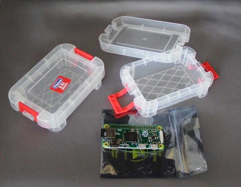
I paid 65p each at a local hardware shop for a 'Really Useful Box company' 0.1 Lt plastic box (these are actually quite hard to find at any price - Rymans being about the only 'chain' store that stocks them (for about double what I paid)). The internal dimensions of 77mm x 52mm x 24mm were just right to hold a Pi Zero (with a right-angled micro-USB cable).
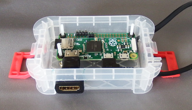
The mini-HDMI to standard HDMI adapter would, of course, require a 'hole' be cut in the side of the box, however this 'lined up' nicely just below the box lid and to one side of the corner reinforcing ribs (see below).
The 'next size box down' (0.07L) can also be used (just) = I paid £5.99 for a pack of 10, so that's 60p each. It's not quite long enough for the dull width of the Pi PCB, however you will need to cut a slot in one end to get access to the SD card (swapping out the SD card is a quick way to 'update' the Photoframe with some new photos). If this slot is made wide enough, the Pi PCB can be fitted into the box with the SD card end 'sticking out' about 1mm.
Alternatively, the Pi Zero PCB can be mounted 'diagonally' from one end bottom corner to the opposite top corner (the avoids the need for a SD card access slot (if the Pi PCB is mounted so the SD end is just under the lid). The drawback is that it's very hard to mount a mini-HDMD to HDMI adpater at the correct angle and position (of course, for a CCTV Pi-Camera, you will be using 'TV out' instead of the HDMI = see my Pi Camera pages)
Pi Power
Since the Dell 2001 display has a built-in USB hub, you might think that powering the Pi would be simple, especially as the Dell display USB sockets are rated at 2.5weach (so plenty enough current to run a Pi Zero). However it turns out that the Dell won't "power up" it's USB sockets until it detects the USB "B cable" (uplink to a computer) = and the Pi can't 'activate' that without power ....
Lucky for me, the Dell 2001 has a +12v DC outlet designed to power a 'sound bar'. To use this, you can buy (for £1) a 12v car USB charger (you will have to look hard for one rated at 1A - most are 500mA) and rebuilt it to plug into the 12v power output. This lets you use an A/A+ (or even a B) instead of the Zero.
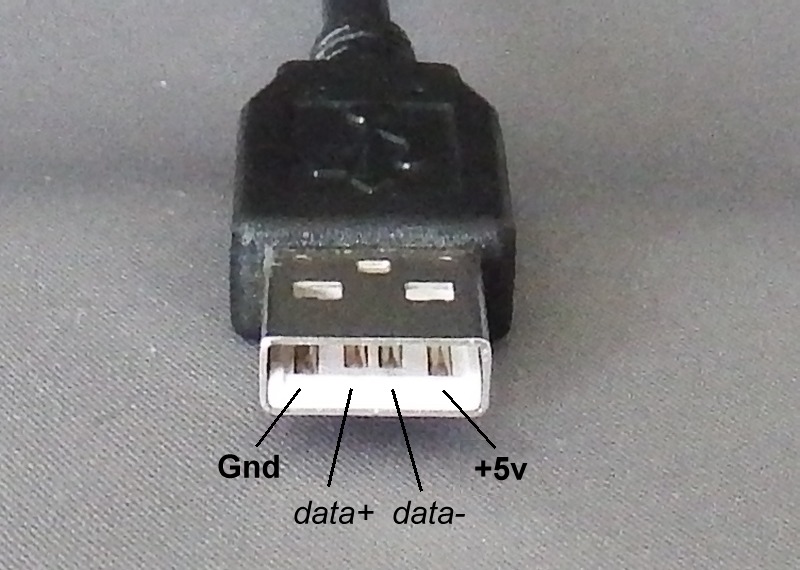
I used a scrap USB cable chopped off an old keyboard (so a USB plug at one end and bare wires at the other), however if you have to buy a cable, £1 gets you a 1m cable with USB plugs at both ends that you can chop into half (so, cost 50p :-) ) NB. on my cable, the black wire=Gnd, red wire = +5v (but it pays to check).
It's a good idea to solder the USB power cable directly into the Pi Zero circuit board 40pin header (Pin2,4 = 5v, any of Pin6,9,14,20,25,30,34,39 = Gnd) thus avoiding one of the main problems with the Pi, the tendency for the power cable to work the socket loose until it falls out under it's own weight.
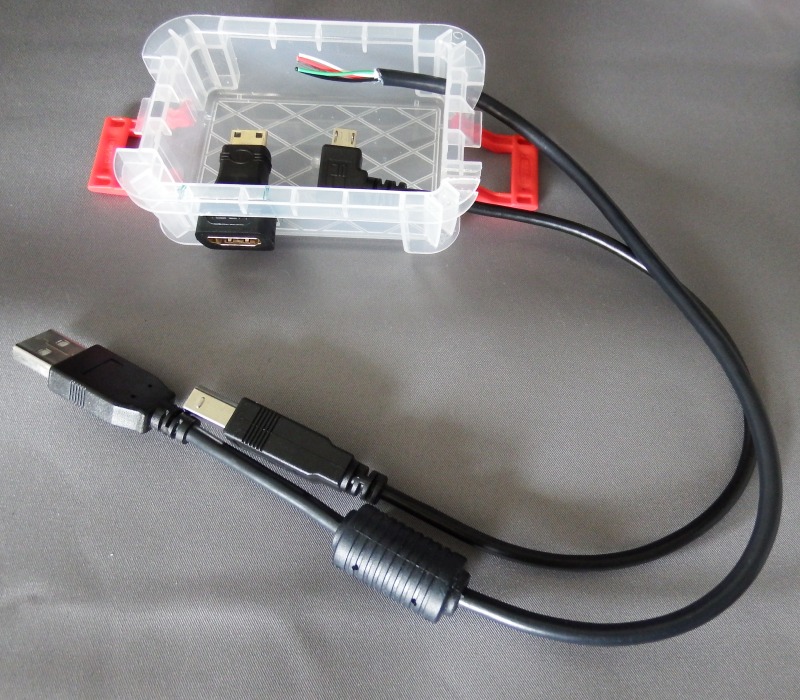
After adding header pins for the 'in use' LED, 'load' push button and remote control sensor (see below), I then soldered the power wire ends directly to the (underside of) the Pi motherboard (this keeps the power cable 'well out of the way' when connecting parts later).
USB hub connection
To connect to the USB hub built into he display, I used a short 'right angled' micro-USB plug to USB 'B' (square style) plug at a cost of about £1 (from China, via eBay).
The right-angle plug obscured the Pi power socket, however that's not a problem as it's not going to be used. However if angled the other way it could interfere with the mini-HDMI connection = so be careful not to end up with a 'left-angle' version :-)
Display drive
Unless your display has a HDMI input (in which case all you need is a short mini-HDMI to HDMI cable), you will need some sort of mini-HDMI adapter.
I already had a HDMI to SVGA converter, so decided to use that. This in turn meant I needed a mini-HDMI to standard HDMI socket adapter at the Pi Zero. To stop the weight of this wreaking the Pi mini-HDMI socket, I fixed the adapter to the case, then the Pi is plugged inside and the mounting screws adjusted as needed

At the monitor socket, a 15pin 'male to male' adapter was used, thus eliminating the need for a VGA cable. Total cost was £7 for the converter + £1 each for the mini-HDMI to HDMI and 15pin the pin-pin adapters (all eBay), total £9.

A mini-HDMI to SVGA socket converter would also have 'done the job', saving the cost of the mini-HDMI to HDMI adapter (£1) but is a slightly less flexible solution (if you fit the mini to standard HDMI at the Pi, you can switch it to a display with a HDMI input - or use a HDMI to DVI adapter instead (see below))

The Dell 2001 has a DVI-D socket. Using this would be cheaper = all you need is a short mini-HDMI to HDMI cable (about £2) plus one of those 'chunky' in-line HDMI to DVI adapters (£1), for a total of £3 (rather than about £10)
NOTE that whilst a HDMI-VGA converter means you can 'split off' the audio, you then need some means of powering the external speakers. If you want Audio, it's better to go the 'USB audio device' route (so the display USB socket powers the speakers)
Mounting the Pi
The function of the box is to support the external cables and adapters (something the over-priced 'Pi Cases' sold elsewhere totally fail to do) as well as providing a way to 'fix' the Pi 'assembly' to the back of the LCD display (double sided tape usually does this job well), in which case you might not bother to fit the box lid.
If you do decide to fit the lid, remember to drill a few holes in the 'bottom' and 'top' sides of the box (when mounted) to allow a bit of air circulation :-)
Mounting the Pi in the box is the next task. The Pi has 4x holes for M2.5 (2.5mm) metric bolts. For maximum mounting flexibility, I decided to purchase the max length M2.5 nylon bolt available, 25mm, and cut them down as necessary. Further, I chose the 'flat slotted head' style (so I had the option of gluing the head of the bolt to the bottom of the box, rather than having to drill the box to take the bolt).
I would need up to 3 nuts per bolt - one to fix the bolt to the bottom of the box (unless glued), then 2 more to hold the Pi PCB at just the right height off the bottom
Looking on eBay, I was amazed to discover a UK seller was able to sell packs of 5 nylon bolts+nuts for £2.50 (in other words, 50p a bolt !). For a pack of 20 nuts he was asking £2 (so 10p for each extra nut). At these prices, mounting the Pi using 4 bolts with 3 nuts each would end up costing me £2.80 !
Of course I had no intention of paying such outrageous prices and, after a bit of searching around on eBay, I managed to find 50pcs M2.5 x 25mm slotted (flat) head Nylon bolts for £3.50 (7p a bolt) and 100pcs M2.5 nylon nuts for £2.66 (so 2.7p each), giving me a total mounting cost of 60p. Adding in the plastic box (at 65p) gets us to £1.25, about 1/3rd the price of the basic (and useless) 'Pi case enclosure' (about £3.50 on eBay)
I saved a few pennies by only using 3 screw/nut sets (all the strain of GPIO plugging in/out will be on the pins rear left, so the front right can be left to 'float'). You will note how the mounting bolts are left 'poking up' in the box - this is deliberate and allows a 'Hat' ('pHAT DAC' Audio output board) to be added later - but being nylon they can be clipped off with side-cutters if you want a 'neater' appearance
Remote Control
I decided to go for an IR system - not ideal (you have to 'point' the controller at the display) but cheap :-) The 17 button KEYES IR remote control and sensor can be found on eBay for less than £2.
The sensor comes with a 3 wire 'socket to socket' cable. This requires 3 '.1" pins' be soldered to the Pi Zero motherboard, +3.3v, Gnd and 'RxD' (serial receive) so the sensor can be plugged in (later)

Note, you can use any suitable bit of scrap wire (such as the ends off a resistor) for the '0.1" pins'
Total cost
My total cost was :-
£25 (Dell 4:3 21" display) + £6.50 (Pi Zero 'one per customer') + £1 (4Gb SD card) + £0.50 (power cable) + £1 (USB hub cable) + £9 (display converter) + £2 (KEYES IR remote control and sensor) + £1.25 (case and mounting bolts) = £47.25.
So, I built a 21" photoframe for less than £50 !
If you drive the display via a £1 mini-HDMI to DVI adapter cable, you save £8 reducing the cost to just under £40 !!
For the Mk2 Photoframe software, see my Next page