

*** UNDER CONSTRUCTION ***
Assembling my Pi astro-camera
Any astro-camera has to be mounted somewhere onto your telescope/mount assembly. In fact, I can think of at least 4 places where you might want to use a camera = on the 'polar alignment' scope (which, on most mounts, is almost impossible to get your eye to after mounting the OTA), on the main telescope 'finder' (which can also be a pain to get your head around), on the main OTA itself (for planetary imaging) and finally on a co-mounted 'guide scope' (for when the main OTA is being used to image DSO's with your DSLR)
When it comes to choosing the mounting method, the obvious choice is to go for the 1 1/4" standard
This means the astro-cam can be used directly with standard OTA (or co-mounted refractor).

To support all those non-1&1/4"-standard polar alignment and finder 'scopes, the best we can do is to make the astro-cam as small and light as possible, so if all else fails, a bit of gaffer tape will do the job :-)
My goal is thus to assemble a Pi Zero + camera into the smallest possible Really Useful box (3" x 2.5" x 1") available. This box would need to include not only the Zero and camera but also a USB Ethernet 'dongle' (to allow the camera to 'communicate' with my PC) and a voltage regulator (to support PoE, which is how I powered the Pi). How I achieved this is detailed below
Pi in a small box
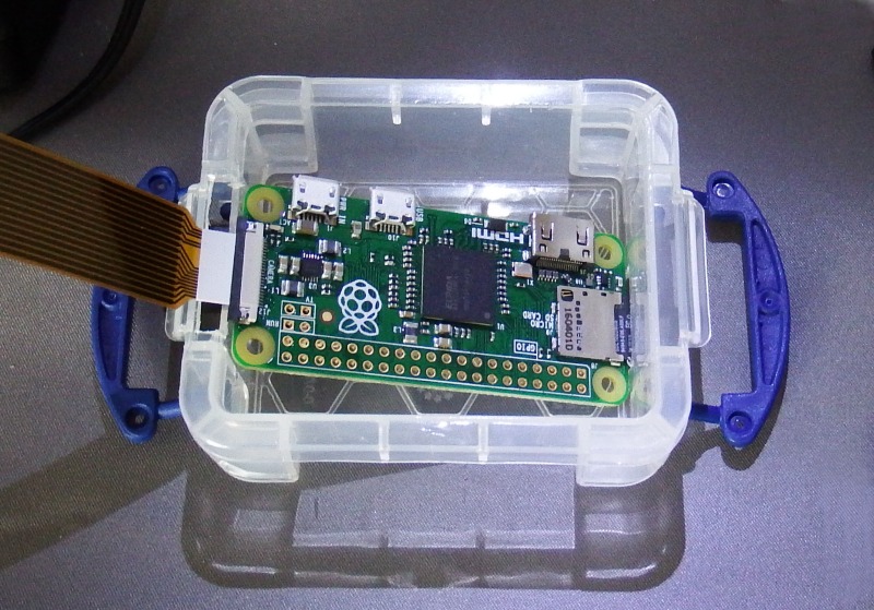
(left) The Pi Zero just fits when mounted diagonally across the length (although the camera cable would have to be bent quite sharply and folded to get it back inside the box).
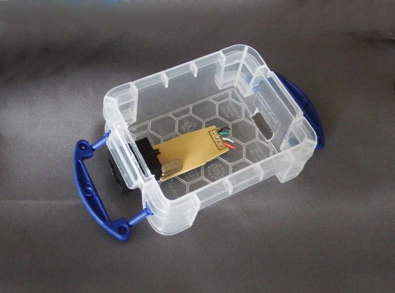
This leaves enough room for the guts of a USB-Ethernet dongle to be fitted below the Pi with the Ethernet socket protruding as far as possible (right)
(right) The slot seen cut into the bottom of the box on the right (opposite the Ethernet dongle) is to provide access the Pi's SDHC card. To avoid placing too much strain on the camera ribbon cable (which has to be folded back inside the box to close the lid), the box edge above the Ethernet socket was cut back slightly
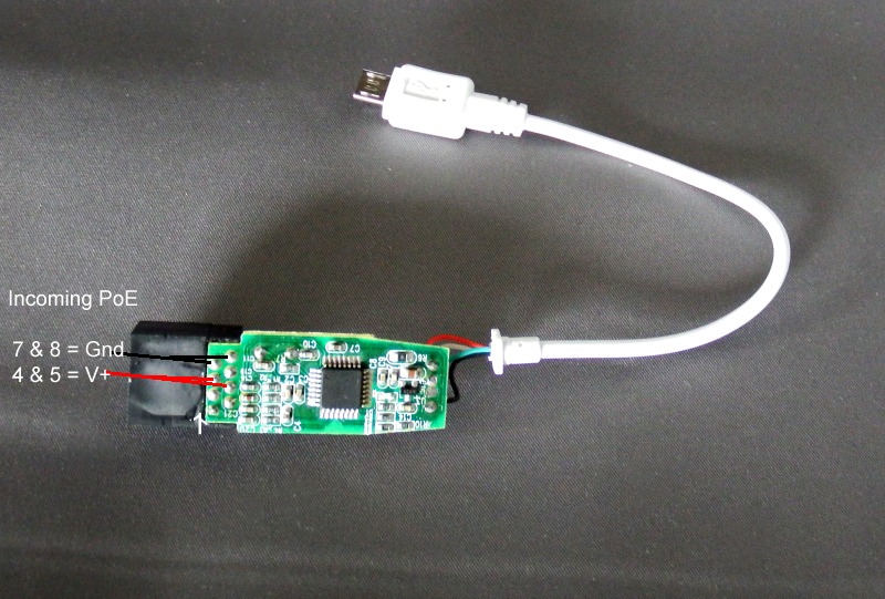
(left) To use Power over Ethernet (PoE), pins 4 & 5 (V+) and pins 7 & 8 (Gnd) have to be 'picked off' from the Ethernet socket and wired to the voltage regulator (see later).
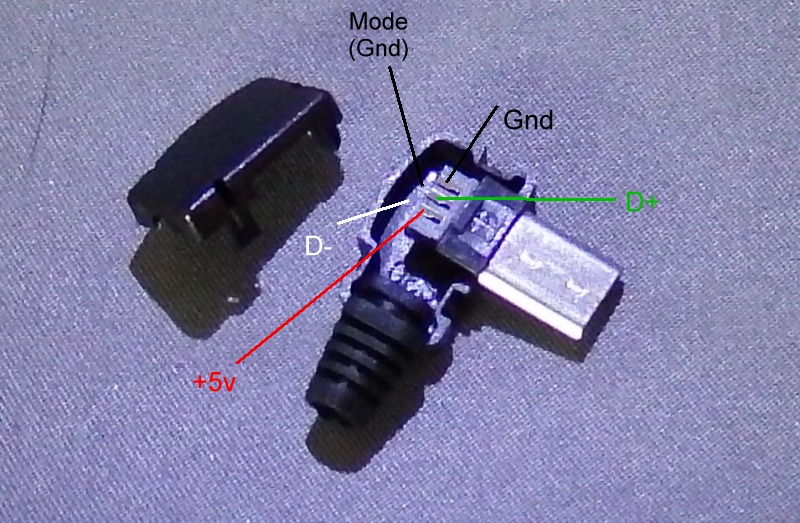
There is no room for the USB dongle plug, so I chopped off the cable and wired direct to a right-angled micro-USB plug (plug pins from the left (when looking at the plug short side up) are 1-Red-+5v, 2-White-D-, 3-Green-D+, 4-mode-(Gnd), 5-Black-Gnd) (right)
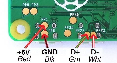
(left) An alternative to using a right-angled micro-USB plug is to solder the Ethernet dongle USB wires direct to the underside of the Pi Zero PCB, using the 'PP' (test) pads on the back of the board. This allows the Pi PCB to be positioned more centrally within the box (the micro-USB plug means it has to be pushed to one side)
Telescope eyepiece
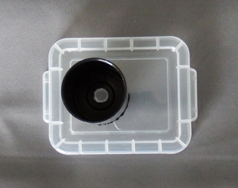
(left) Those of us who used SLR 35mm film back in the 'good old days' will still have some old film canisters knocking around somewhere. Go find one, it's exactly the right size to fit inside a 1.25" eyepiece focuser !
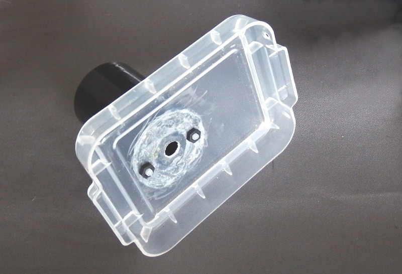
Finding a glue that will stick to both the box and canister proved impossible (even using an outdoor 'gutter sealant' failed) and I ended up using a couple of Pi mounting bolts (right)
PoE regulator
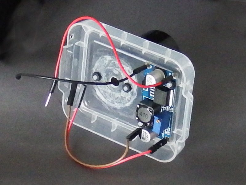
(left) With the Ethernet dongle fitted underneath the Pi, and the camera module to the lid above (and the micro-USB right-angle connector using up space in the middle), I ended up having to fit the PoE voltage regulator to the lid - when the lid is closed, the voltage regulator assembly just fits 'upside down' above the SDHC card slot at the end of the Pi.
Since the voltage would need to be adjusted before use, I opted to use 0.1" 'wire sockets' to plug the output into the GPIO header pins. Due to the lack of space the Pi header pins had to be bent at about 45 degrees (the +5v exists only on header pins 2 and 4, however Gnd can be found on multiple pins (I used pin 14)).
Camera board mounting
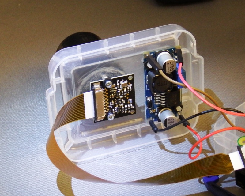
(right) As expected, mounting the camera turned out to be a real pain = it uses 2mm bolts (the Pi itself uses 2.5mm) and whilst you can find 2mm nylon bolts these are not at all 'robust'. This means using metal bolts and finding a 'spacer' to avoid shorting out the camera component 'lands' that are too close to the mounting hole positions
Trying to 'line up' the camera using 4 bolts is an exercise in frustration = you need 3 adjustment screws arranged in a 'triangle' (of course) = but then the Pi Foundation really don't have much of a clue when it comes to practical things such as how their products might be bolted onto anything else (indeed, on the first released Pi A/B PCB mounting holes were a total 'afterthought', so we are lucky that the camera PCB has any mounting holes at all).
Putting it all together
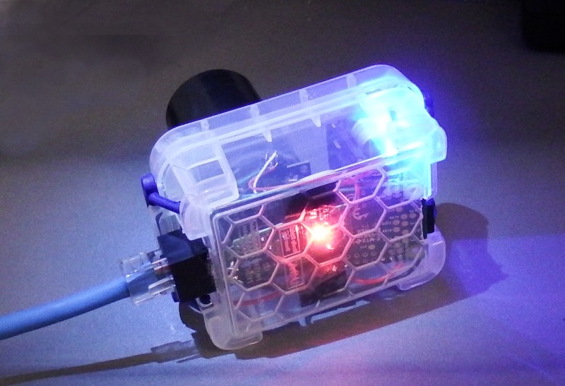
(left) The finished unit, assembled and running from a PoE cable. I had only two slight 'final assembly' problems = first the camera board is rather too close to the Pi power micro-usb socket (a bit of insulating tape was used to avoid shorts - better would have been to remove the socket) and second the camera ribbon cable kept trying to 'escape' every time I tried to close the box (and would get trapped in the lid) = this I 'fixed' by pushing it in with a small bladed screwdriver whilst closing the lid
The bright blue-white LED in the top right corner of the box is the PoE power regulator, and the bright red LED in the center is the USB Ethernet dongle - both of which I forgot to cover before closing the box :-(
Video out
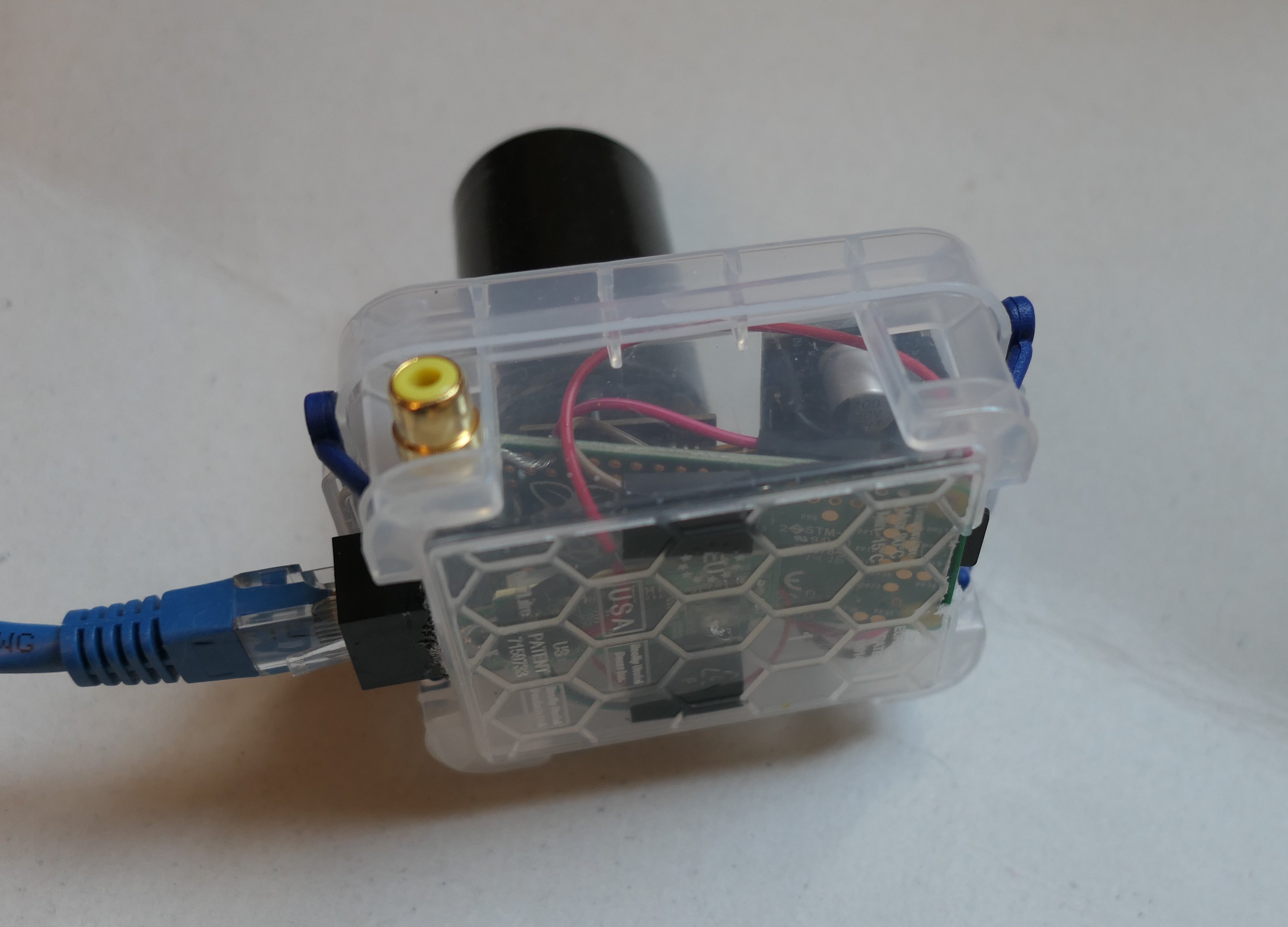
A late addition was a RCA AV socket for local 'Video out'. I managed to squeeze this in next to the PoE 'dongle', directly below the 'TV' 0.1" hole on the Pi PCB. I added a small slide switch (not visible - it's mounted exactly opposite the RCA socket). Wired to a GPIO pin, this controls the 'mode' - Video or Still Image.
I fitted the RCA socket after I discovered what a frustrating process it was to focus the Pi+telescope by checking a series of images on my PC. The RCA socket allows 'start of session' focusing using 'live view' (on a locally attached monitor) with the Pi Camera running in Video mode. Aiming at the Moon and using 'live view' provides 'instant' feedback making focus a simple task.
The cost
At the time of writing (Sept 2016), the Pi Zero was still being sold on a 'one per customer' basis, so whilst the 'headline' price is £4 each, real world price is £4 + £2.50 postage = £6.50 each.
When it comes to the Pi camera, with the release of the v2 (8Mpixel) version in May 2016, you might expect the now 'obsolete' 5 Mpixel version to be sold at 'remaindered' prices = no chance - in fact some sellers (eg Amazon) are asking MORE for the old version. So I've listed the v2 cost.
Finally, for 'parts' start with Chinese suppliers (via eBay) = they ship POST FREE, unlike (most) UK suppliers (UK Postal Service charges are killing the UK 'small parts' suppliers).
Pimoroni - Pi Zero (£4), camera adapter cable (£4**) + p&p (2.50) = £10.50
**Yes, £4 is a rip-off for the camera cable, however I've not yet found it cheaper elsewhere.
WARNING Don't be tempted by any of their rip-off priced 'Pi Zero kits' (especially not their 'CCTV kit' which DOESN'T INCLUDE THE CAMERA !)
The Pi Hut - Pi NoIR 8Mpixel camera (£21) + p&p (2.50) = £23.50
Rymans - 0.14L Useful Box (pack of 5 for £4, delivered to your local store) = £0.80 each
eBay (HK, China) - LM2596 Regulator (10off for £6.29) = £.0.63p each
eBay (HK, China) - 'Ethernet Adapter for Tablet PC' (5off at £6.90) = £1.38 (best 1off price is about £1.53)
eBay (China) - Micro USB B Type 5-Pin Male Soldering (20pcs at £2.91) = £0.15p ea (note - these are bare plugs - I paid a bit extra for right-angled housing version) and you don't need it at all if you solder direct to the 'PP' pads on the rear of the Pi PCB
eBay  (China) - Male 0.1" Breakable Header Connector (99p for 400 pins or £2.49 for 400 right-angled pins) = I used 2 pins for total less than 1p
eBay (HK, China) - Dupont wire 20cm Cables Line Jumper 1p-1p pin Connector Female to Male (40pcs for £0.99) - I used 4 wires, so £0.10p total.
eBay (HK, China) - Ethernet PoE Adapter Injector + Splitter (2 adapters for £1.22) so £0.61p (note = single in-line PoE adapters ('IP Camera LAN Network PoE Injector Splitter') can be found for 99p each.)
ebay (China) - UK 12V 2A 110-240V AC DC POWER SUPPLY = £2.19 (note = 24v power supplies are more than double the cost but are a 'good idea' for Ethernet cable runs exceeding about 30m)
Total cost (8Mp camera) £39.87 - or with 5Mb camera (see note 4 below), £22.75
Notes.
1) I've not included any Ethernet cable as the cost will depend on the length you need (I suggest allowing 20p per meter = you can get 5m at the £1 stores)
2) Yes, the total cost of each order sent from China (and that includes the Power Supply) is indeed less than the UK postage charges added to each order by the UK Pi distributors ...
3) If the value of a (single) package sent from outside the EU exceeds approx £18, you will have to pay 20% VAT plus a 'handling charge' of (typically) £8 (which tells you all you need to know about how our Government maintains prices in 'Rip Off Britain')
4) After building my Astro-cam using the 5Mp NoIR camera from 'RS components' and being ripped off for the Pi Zero camera cable, I found the same camera including the Pi Zero cable on eBay (from China, post free) for £10.38. This would reduce the cost of the camera + cable from 23.50+4 to 10.38, a saving £17.12p !
Local power
After building the Pi Astro-Camera with PoE, I realised that my telescope is powered by a +12v battery = the same voltage I was 'injecting' at the Ethernet (PC end) for the Pi PoE !
So, to run the Pi Astro-Camera in a totally stand-alone mode 'in the field', without any PC Ethernet connection, all I needed to do was use the telescope battery as the power source !
This could be done by wiring up a short Ethernet cable with a PoE 'injection' at the battery, or just by fitting a '12v power in' socket to the Pi Astro-Camera (the ideal approach, since this would pave the way for telescope PoE = see below)
Careful design of the imaging software would ensure the Astro-Camera could operate in 'stand-alone' mode.

All I would need to do was ensure the 'imaging' task would write to SDHC, whilst a separate task would move (or copy) images from the Pi SDHC to the Windows 'share' via the Ethernet cable.

If the Ethernet link was 'down', the second task would have to wait, but this would not stop the first from generating images.

Of course the SDHC card would eventually overflow, however I would worry about that later :-)
Telescope PoE
When at home, I could do the reverse = instead of using the telescope battery to power the Pi, I would use the Pi PoE to power the telescope !
So a single '12v power' socket on the Pi Astro-Camera becomes a '12v power in/out' socket
Actually, it turned out not to be quite so simple. Sending +12v down a 5m test cable 'worked fine', but trying to do the same with a 50m 'in-the-field' cable drops the voltage way too much. Whilst the Pi regulator will keep running the Pi (5v) from a PoE input down to 9v, the telescope was not at all happy with anything less than 11v.

In the end, I had to 'up' the 'injection' voltage to 24v. THe regulator on the Pi was rated up to 35v inpit, so that was fine. The Pi '12v power socket' thus becomes a '12/24v power socket' (rather than 12v in, 9-10v out :-) ), which meant I needed a 24 to 12v regulator at the telescope end when running the 'scope off the 24v PoE (instead of running the Pi off the telescope 12v)

To avoid lots of extra plugs and sockets (which would inevitably end up falling apart during an observing session) I ended up making a 'special' power cable (with regulator built in) for the telescope - but that was another Project !.