

Although suitable for any Pi, the intent is to make this a small portable battery operated device. This makes the Pi Zero the ideal choice (or the A+, if you can't get a Zero)
The Pi presentation slideshow controller
A natural evolution of the photoframe, this 'Pi in a box' is intended to be plugged into an overhead projector ('beamer') and be used to show a series of photos (or other presentation image material), from a USB stick, in a 'slide show' mode
Note that whilst it is intended to have the Pi display a series of simple jpeg images (or perhaps an mpeg movie), with a bit (actually, a lot) of work it might even be possible to use LibreOffice to show Power-point slides !

However, initially, I just used the 'photoframe' approach to display the photos / videos etc. found on a 'hot plugged' USB stick.

The major difference between this and a slide-show is that presentations require some sort of hand controller (to step forward and backward amongst the photos).
Note. The system must support 'hot plugging' of a USB stick. This means all the scripts must be 'self starting' (since inserting a USB stick can cause a voltage dip sufficient to cause the Pi to 'reset' itself)
Overview (phase 1)
The goal is to show each .jpg photo found in the root of the (just plugged in) USB stick one after the other. Two scripts will be required, one (1) running in the background fetching photos and the second (2) controlling the display
1) The first scrip is designed to run in the background waiting for a USB stick to be inserted.

Photos will be processed (and later displayed) in simple 'alphabetical order' of file name (so 0-9, a-z, A-Z). Initially, any existing file of the same name will be overwritten (to 'delete' a file already on the Pi, a zero sized file of the same name is placed on the USB stick).

Jpegs will be copied from the 'source' (root of the USB stick) to the 'destination' (the 'display' folder). Correctly sized Jpegs will be copied directly (ImageMagick 'convert.exe' utility will be used to re-size any .jpgs not already of the correct (exact) screen display size).

To avoid the display script showing a part copied or processed photo, the destination will be named '{photo}.tmp' and only renamed to {photo}.jpg once copying/processing is complete.

A LED will be turned on so the user knows when the Pi is 'loading' (if the Pi Zero is used, the existing 'Activity' LED could be 'blinked')

When all the screen sized thumbnails have been generated, the LED will be 'turned off' (on the Pi Zero, that would mean switching the LED from 'blinking' to 'steady on') and the script will then wait for the USB stick to be removed.

Once the USB stick has been removed, the script will loop back to the start (1).

2) The second script is the 'display' (control) script. This will loop forever showing whatever it finds in the 'display' folder 'next' (as controlled by the user keypad).

The photo display time is set by the display script itself (or maybe by some 'flag' in the file name).
To ensure a seamless and smooth display transition, from one photo to the next, the 'fbi' script with the 'tmpfs' (RAM disk) trick will be used, along with the Pi Zero Photoframe project 'check for next photo' script.
Overview (phase 2)
When a hand controller is plugged in, stepping from one display photo to the next will be manually controlled.
For stepping, at least 2 buttons are required (step forward, step back) - if video is to be shown, an extra button will be needed for 'pause/continue'.
To support a Menu, at least 2 additional buttons will be needed (a Menu will allow, for example, a USB sub-folder to be selected as the 'source')
 A new 'Menu' button is needed to switch between display mode and Menu mode (the existing Forward and Back buttons allow Menu navigation)

A new 'Enter' button is needed to switch the menu option settings (set / clear) - the state of the option is 'saved' when 'leaving' that option and after changes, pressing Menu (to exit) will bring up a 'Save / Abandon' dialogue
Note: The simple way to show a 'Menu' (without the need for any clever GUI), is to just display a series of .jpg photos, each being the photo of a 'menu option' (it is even possible to have to Pi create such "menu photo's" 'on the fly' using ImageMagick) :-)
The hand controller
I considered the following :-
1. A fully DIY, cabled, push button controller.
The controller would need at least 4 buttons, so 4 wires + ground (an Ethernet cable, 4 twisted pairs, would do the job). If some means of detecting the controller is provided, a total of 5 i/o pins are needed (all using internal pull-ups) = one pin would be grounded by plugging in the controller, and each of the 4 buttons grounds it's own pin.
Unfortunately, a cabled controller is not very 'presenter friendly'. Further, building one from scratch would be quite time-consuming
2. Off-the-shelf iR remote.
A basic 17 button IR remote for the Pi can be had for less than £2 (eBay, "Infrared Wireless Remote Control Kits for Arduino Raspberry pi AVR PIC", £1.82 each, postage included from China).
The 'KEYES' 17 button controller uses one GPIO pin and transmits a simple Hex code string when the corresponding button is pushed. The receiver is a simple IR diode that pulls a GPIO pin to ground.

The code is transmitted using the standard serial link protocol (1 start, 8 data, 1 stop) at 9600 baud, so requires more complex software than a '4 GPIO for 4 buttons' solution.

It's main disadvantages are the limited range, the fact that it has to be 'pointed at the Pi' and that there is no way to detect the existence of the controller until a button is pushed = it would be possible to make the IR Receiver 'detachable' and incorporate a 'pull to ground' when plugged in, however, for simplicity, the IR detector would be permanently attached. Fortunately, enough 'spare' codes exist to allow one to be dedicated to a 'mode' function (enable hand control / disable hand control).

It's big advantage is that it's cheap = in fact it's cheaper than using individual buttons !

Furthermore, the 'key detect' software is plainly reusable (a 17 button 'menu' driving controller can be used for all sorts of Projects !), so this is my 'preferred solution' (in fact, the same controller is available as part of a kit, with a 2 line 16 character display** and multiple prototyping parts (eBay, "Raspberry Pi B+ 2/3 kit GPIO Board 1602LCD= "and similar, from China, £11.50 inclusive), suitable for a Pi Jukebox / Internet radio).

**Note. The display included with the kit mentioned is an '8 bit parallel data' type = i.e. you need additional circuits (such as a PIC based serial to 8 bit parallel 'converter') or will have to dedicate Pi GPIO pins to the display
3. Off-the-shelf Bluetooth (wireless) controller.
These are more expensive - even a basic 4 button unit is at least double the cost of the 16 button IR unit - and also requires more complex software
The Bluetooth advantage is that the controller doesn't need to be 'pointed at the Pi'.

The Pi system software supports Bluetooth, so coding up the button 'actions' would required a similar effort to that needed to support the IR keypad buttons, however with only 4 buttons there is limited opportunity for reuse.
I decided to go with the iR controller, mainly due to it's low cost and the existing software - Linux Infrared Remote Control (LIRC) Daemon, which is included in the Pi Jessie distro.
Battery operation
The intent is to make the projector 'Pi plug-in' unit totally self contained. This means running from batteries. Again, I considered various solutions :-
1) Using 3 x 1.5v non-rechargeable batteries. When 'new', these should deliver over 1.6v each (so 3x is at least 4.8v), however the Pi minimum is 4.75v so even brand-new batteries would not keep it working for long. Moving up one is 4 x 1.6 = 6.4v and bye bye Pi.

2) Using of 4 x 1.2v = 4.8v NiMH rechargeable batteries. Whilst the 'discharge curve' of NiMH means they deliver at least 1.2v for 50% of their 'life', when fully charged, NiMH batteries can deliver more than 1.3v each = so 4x would mean 5.2v and that's getting close to the Pi maximum (about 5.25v) although we should be safe.

3) Using 6 x 1.2v = 7.2v NiMH with a low-drop-out 5v voltage regulator. This will work just fine, but 6 batteries occupies a lot more space than 3 (or 4)

4) Using a 'Power bank' (LiPO USB battery pack). This is an 'off the shelf' solution.
I decided to go with (4), the Power bank, simply because it's 'guaranteed' to be 5.0v - however I chose a project box with enough space for 6x NiMH batteries and a LDO reg. 'just in case'
Using a Power Bank means a 'neater' solution as it can be recharged by plugging in a USB cable (through a small slot cut in the Pi box).

Fitting a couple of diodes (or MOSFET switch) means it's even possible to run from a USB power block instead of the battery (see my Pi UPS page, 'Notes on using a PowerBank' paragraph, 'Diode switch' note)

To recharge other batteries means 'opening the box' - and being lazy that's going to get 'put off' until I panic an hour or two before it's needed :-)
Reducing battery consumption
A typical 'dual cell' Power Bank is rated at 5,200mA Hr. at 3.2v (the LiPO battery voltage). A more realistic usable capacity at 5v would be about half this (so 2500 mAHr). Using one with an 'on/off' switch means you don't need to design in another power button
The Pi Zero / A+ consumes something like 110mA. A HDMI to VGA converter will add another 40mA or so. A HDMI-DVI adapter will consume nothing, so use a DVI connector (if you can)
You can save about 25mA by turning off the Pi's own internal HDMI circuits (/usr/bin/tvservice -o) and turning them on only when needed (/usr/bin/tvservice -p), (however that likely has zero effect on the power consumption of any attached VGA converter).
You can save another 5mA by turning off the ACT LED on the Pi Zero (the LED is 'on' by default, turning 'off' only to indicate 'disk activity' so it's actually throwing away battery power almost all the time = see below)
To disable the Pi Zero LED, modify /boot/config.txt file (and reboot) adding the following :-

# Disable the ACT LED on the Pi Zero.
dtparam=act_led_trigger=none
dtparam=act_led_activelow=on
Also, any plugged in USB memory stick will consume power = so it's a 'good idea' to 'load from USB' and then unplug the device (assuming this doesn't cause the Pi to crash :-) )
It is noted that pin 9 of the 15 pin 'VGA' socket on a video card outputs '+5v' (on older kit, pin 9 was the 'key' pin). Devices that comply with the DDC host system standard provide 5V ±5% and a minimum of 300mA ('host system' means 'video source', as opposed to 'destination', such as a projector / beamer). The same applies to the +5v on the DVI connector. So, unfortunately, we can't use the 'beamer' to power the Pi ....
Worst case, I assume the Pi box consumes 150mA = so a typical '5200mAHr' Power Bank (out of which I might get 2600mAHr) will run for over 16 Hrs and a 1500mA Hr NiMH power pack (about the lowest spec you can find) will last 'up to' 10 hrs. Either will be plenty, especially if you make a point of recharging the batteries after each use
Choosing the box
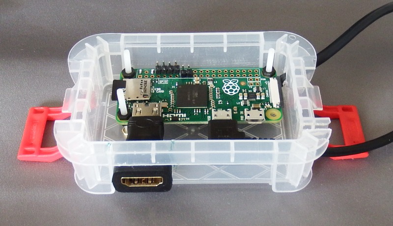
All 'off the shelf' cases for the Pi Zero are utterly useless. The 'typical' offering costs more that the Pi Zero itself and consists of two bits of perspex forming an open 'sandwich'. This does nothing to support a mini-HDMI to HDMI converter nor does it support the power plug = but worst is the open construction that allows the ingress of any sort rubbish that could 'short' the PCB tracks or i/o pads. Just avoid them like the plague they are.
Starting with a 'Really Useful Box' you can build your own Pi enclosure for less than half the price and provide all the support for adapters you need and even have room to bolt a PHatDAC (audio output) board on top
To get 4 or 6x AA batteries inside, either a 'long flat' box (with batteries alongside the Pi) or a more 'chubby' (taller) box (with batteries 'suspended' from the Lid, above the Pi) is needed.
The alternative is to use the smallest possible box that will accommodate the Pi alone and use this with an external power-supply (USB mains power block, LiPO PowerBank or even a DIY UPS / battery pack)
For maximum flexibility, I decided to go for the 'small Pi box + external power' option.

Using the Pi zero, a mini-HDMI to HDMI adapter will be needed (see below) and this must be supported by the box.

Shopping around, it is possible to find a micro-USB to standard USB socket adapter that's about the same length as the HDMI adapter. This allows them both to be mounted inside (and be supported by) the box.

The Pi Zero's power socket will likely be obscured by the micro-USB to USB adapter (and is too far to reach inside the box to reach anyway). So powering the Pi zero means wiring to the 5v/Gnd i/o header pads. Either a cable with standard USB plug can be fitted, or wires run to a micro-USB socket mounted just inside the box.
Video output
Older projectors had 15pin SVGA sockets (and sometimes DVI as well), however modern ones have only HDMI. To address a range of projectors, the 'boxed' Pi should 'expose' a HDMI socket, thus allowing the option of an external HDMI - VGA converter to be used.
If you use the Pi zero, you need a mini-HDMI to standard HDMI converter. Since this will likely be plugged directly into the Pi, it MUST be supported by the box (or you risk damage to the mini-HDMI every time you plug something into the adapter). So this means your project box has to take into account the extra 'width' added by the converter.
Some means of setting the video 'mode' will be needed
Whilst using the 'remote control' with a 'menu' is the 'obvious' approach, this fails when the Pi system is left set to HDMI frequencies and a VGA projector is used.

Whilst the Pi could 'default' to VGA on every power-on (or a 'reset' switch could be fitted), things then start to get 'complicated' (especially if inserting a USB sick causes a power-on reset :-) )

Dedicating a couple of I/O pins to 'video mode' might be 'crude' but is rather more likely to 'work every time' :-)

I thus add two switches :-
1) 16:9 / 4:3
2) Lo / Hi

This gives me 4 settings :-
16:9 + Lo is 720p (1280x720), 16:9 + Hi is HDMI (1920x1080)
4:3 + Lo is XGA (1024x768), 4:3 + Hi is SXGA+ (1400x1050)

This should ensure the widest possible coverage of possible projectors ('beamers'). Once the Projector is up and running with one of these 'working' resolutions, the Menu system can be used to select a 'better one'.
IR Controller
The KEYES 17 button IR controller transmits a serial code when a button is pressed. If the same button is held down, a 'repeat' code is transmitted - so if a button is not 'spotted' when first pressed, holding it down isn't going to do any good. This means that some sort of 'feedback' LED is needed, so the user can immediately 'spot' when a key code has been 'seen' (or not) and thus avoid the temptation to press the same key multiple times (or press it again as needed).
By positioning the feedback LED next to the IR sensor, it can be used as a 'target' to aim the IR controller = which means it needs to be lit 'in the dark', so will 'double up' as a 'heart beat' indicator (blinking = running, long solid 'on' = key received)

KEYES 17 button IR remote control button codes
0xFF629D: = "UP"
0xFF22DD: = "LEFT"
0xFF02FD: = "-OK-"
0xFFC23D: = "RIGHT"
0xFFA857: = "DOWN"
0xFF6897: = "1"
0xFF9867: = "2"
0xFFB04F: = "3"
0xFF30CF: = "4"
0xFF18E7: = "5"
0xFF7A85: = "6"
0xFF10EF: = "7"
0xFF38C7: = "8"
0xFF5AA5: = "9"
0xFF42BD: = "*"
0xFF4AB5: = "0"
0xFF52AD: = "#"
0xFFFFFFFF: = "REPEAT" (button held down)
The infrared receiver (Xinda / KEYES KY-022 TL1838 VS1838B 1838 Universal IR Infrared Sensor Receiver Module. A typical 3 wire module is marked '-' = gnd, mid=3.3v, 'S' = 'sense' (serial Rxd)
lirc.conf for KEYES remote control
begin remote
name  KEYES
bits           16
flags SPACE_ENC|CONST_LENGTH
eps            30
aeps          100
header       9087  4478
one           609  1632
zero          609   526
ptrail        610
repeat       9089  2212
pre_data_bits   16
pre_data       0xFF
gap          108011
toggle_bit_mask 0x0
begin codes
KEY_UP                   0x629D
KEY_DOWN                 0xA857
KEY_LEFT                 0x22DD
KEY_RIGHT                0xC23D
KEY_OK                   0x02FD
KEY_1                    0x6897
KEY_2                    0x9867
KEY_3                    0xB04F
KEY_4                    0x30CF
KEY_5                    0x18E7
KEY_6                    0x7A85
KEY_7                    0x10EF
KEY_8                    0x38C7
KEY_9                    0x5AA5
KEY_0                    0x4AB5
KEY_BACK                 0x42BD
KEY_EXIT                 0x52AD
end codes
end remote