

What's needed for an electric relay drive
Although the Barn Door was designed to be 'driven' manually, the ultimate goal was always to 'motorise' it.
What are the basic requirements ?
Ignoring questions of build accuracy (and polar alignment) and assuming correct gearing etc. eventually the tracking accuracy will come down to achieving, and maintaining, the correct motor speed.
So, all that is needed is a motor that will turn the Drive nut at exactly 1 rpm. This is easier said than done :-)
A simple DC 'servo' Motor might well keep 'reasonable' speed on the living room floor but, exposed to a variable voltage battery supply (as the battery runs down) and variable ambient temperature (such as the night air in the back garden), the speed will be all over the place.
Of course a suitable voltage 'regulator' would allow the voltage (and thus the speed) to be set to some fixed value. However each night we would still have to wait for the circuit to stabilise (i.e. for the batteries to 'cool down' & the voltage regulator to 'warm up'), and then 'calibrate' the drive (i.e. adjust the voltage regulator until the required speed is obtained).
Further, 'calibrating the drive' is also easier said than done.
To calibrate, first do the polar alignment, then pick 'any star' (near the horizon) and engage the drive. If the star 'drifts' East / West, this may be assumed to be due to incorrect drive speed, however it could also be due to errors in the drive bolt 'angle of bend' or errors in the gearing (teeth spacing) or even changes in drive friction / motor loading.
Even if we manage to set the speed 'correctly', there is a good chance that it will 'wander', due for example, to gearing errors or as the drive nut encounters more or less resistance and places more or less load on the motor (which then slows down or speeds up accordingly).
Plainly, with no 'absolute reference' (and no feedback allowing comparison against that reference), any errors in drive speed will accumulate during the entire Exposure time. Even assuming we can achieve 5% speed accuracy, after 10 mins we could be up to half a turn (half a minute) out.
Of course a Stepper Motor can be used, but these are rather more difficult to control (even so, see later).
What is needed, then, is some sort of 'automatic speed adjustment' system.
What are the speed adjustment requirements ?
If the Drive nut position is monitored and compared to an accurate Clock reference, then clever electronics can be used to vary the Motor voltage to obtain the required speed and compensate for any 'drift'.
This will not compensate for errors in screw rod 'angle of bend' but it will eliminate the need for tedious Motor voltage calibration and allows the drive gearing accuracy to be ignored (essentially, any old gearing will do, since any gearing errors are eliminated by monitoring the actual Nut turning).
Complicated electronics are a bit beyond me = so I have adopted a simple approach based on switches and Relays (see below) that anyone should be able to follow !
What is the basic 'clockwork' (or "hurry up and wait") Drive ?
The Drive nut is rotated by a simple geared DC motor powered from a (rechargeable) battery pack. Cheap gearing can be obtained by purchasing Meccano gear sets on eBay. The Meccano Motor can even be used & driven from a 6v battery 'stack'.
Power to the motor is controlled by an 'on/off' Relay.
The Relay (and hence the Motor) is controlled by a pair of switches. The 'Motor On' switch will be triggered by a Clock and 'Motor Off' from the Drive Nut itself.
Since we require 1 rpm. plainly 'Motor On' is generated once per minute (by the second hand of a Clock sweeping past some switch) and 'Motor Off' is generated by a switch on the Drive Nut, once per full rotation.
Even at high magnifications (long exposures) it is acceptable to be 'out' by 5 to 10 seconds (in time) per minute, SO LONG AS the error does not accumulate.
How do i get a 1 rpm clock trigger ?
If the Clock mechanics are robust enough, a 'once per minute' trigger can be achieved by attaching a small magnet to the end of the Clock second hand which then passes over a magnetically operated 'reed switch'. Such reed switches can be found in the 'door open' sensors of typical Burglar alarms)
Reed Switch
 Photo left is a House alarm 'door sensor' set. Furthest left is the magnet housing. Next is the bottom view of the reed switch housing, then the reed switch mount and finally a reed switch itself.
The photo above is a close up of the Reed Switch itself. If you look close, it is just possible to see the switch contacts (one above the other in the middle of the glass envelope), but not the tiny gap between them :-)
How to set up the Clock second hand magnet ?
 A typical modern (1.5v battery operated) quartz type clock mechanism with it's tiny light weight second hand.
Plainly the magnet that came with the security alarm reed switch will be much too heavy .. so a smaller type will need to be obtained.
Alternatively, some other means used of detecting the second hand 'sweep' can be used. For example, a photo-detector could be positioned so that the second hand sweeps past the photo 'eye' to generate the required 'trigger' (a pair of photo-detectors can be found in an old 'ball' style PC Mouse).
One good source of tiny powerful magnets is the children's 'Magnetix' toy ('ball & bar' construction set) - each bar has a tiny magnet at each end (another source is you wife's magnetic earrings or handbag clasp) :-) ).
This has to be fixed (glued) to the end of the second hand.
NOTE If you use a compass for initial 'find north', it has to be kept well away from the magnets :-)
'Hurry up and wait' - how does it work ?
The clock second hand magnet closes the reed switch which trips the relay 'motor on' and starts the motor.
The motor drives the wheel nut slightly faster than 1 rpm. So it will 'hurry up' and finish one complete turn before the clock second hand arrives at the reed switch again.
The wheel magnet closes it's own reed switch which trips the replay into 'motor off'. The drive wheel 'stops' and waits for the next clock 'motor on'
In fact the wheel must continue to turn until the magnet clears the reed switch, otherwise the relay will be stuck in motor off mode. See below for how this 'over-run' is achieved.
When the Clock second hand 'catches up', it will trigger Motor On (and the wheel starts it's next turn).
Thus, so long as the drive wheel turns faster than the Clock second hand, it will always complete each turn first and will always be 'waiting' for the Clock second hand to 'catch up' again. Hence the name "hurry up and wait" drive :-)
Changes in Motor speed will not lead to any accumulating error (for example it does not matter too much if the Drive nut completes one rotation in 50 seconds or 55 seconds), so long as it doesn't run too slow - should the Motor take more than 60 seconds to complete any turn, then, unless some sort of 'speed up' circuit is fitted, it will never catch up !
What's the Motor off 'over-run' system ?
 To avoid the wheel stopping with it's magnet over the reed switch, an 'over-run' diode is fitted (see diagram right).
When the wheel reed switches the Relay 'off' and the 6v is removed from motor power, 3v flows to the motor via the diode. This power continues to flow until the wheel magnet clears the reed switch.
When the drive power drops from 6v to 3v the motor slows down before stopping (when the 3v is removed).
The motor remains off until the clock reed switch triggers the relay back 'on'.
The diode is necessary to prevent 6v motor power being fed back up to the relay 'off' input.
What about the Drive mechanics ?
Before fitting the drive belt, the manual 'arm' was removed from the drive wheel and then the inner 'track' of the wheel was built up with filler (grey, below). This was then ground down level until it was of the correct (constant) diameter.
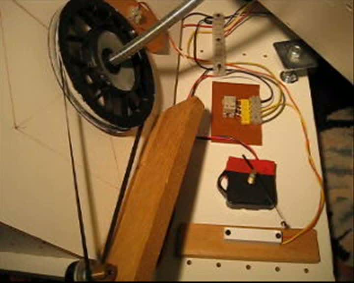 In the photo you can see the drive wheel magnet (silver blob at 2 o'clock on the black drive wheel, just above the screw rod) has just moved past the reed switch (held by plastic 'chock bloc' on wood block above the magnet). This has just triggered the reed switch to switch the relay off, thus removing the main drive power (and allowing power to flow via the 'over run' diode so the magnet overruns the reed switch).
The second hand of the free running clock (sweeping clockwise) can be seen just approaching the 'on' reed switch (inside the white block) bottom right.
The relay board & over-run diode is above the black clock (with red tape holding in the power wires). When the clock second hand passes the 'on' reed switch (inside the white block) the relay is trigged 'on' and the drive starts.
The drive wheel (which runs faster than the clock) then turns until it's magnet reaches the off reed switch again - at this point the relay is triggered 'off' (but the drive continues on the over-run diode power until the magnet clears the reed switch).
If you are very patient (it takes about 10 minutes), you can right click and 'save as' to download a short clip of the finished relay drive running here :- .WMV, or .AVI
What position error causes star trails ?
The main disadvantage of the above method is the 'default' speed margin required. Since the motor must drive the Nut faster than one rpm, there will always be some unavoidable positional error.
Assuming a 10% default speed margin - in which the Motor drives the Nut to complete one turn in 54 seconds, after which it waits for 6 seconds for the next trigger - the max. positional error (at the end of each turn) will be 1/10 th of a turn. This will not accumulate, so even after 10 mins. of running, the max. positional error will still be the same 6 seconds (1% in 10 mins).
The problem is, a 6 second 'stop' will cause a 'star trail' in excess of 1 pixel when using a telephoto lens at any Declination.
Of course it is highly unlikely that the BarnDoor will be stable enough to avoid 1 pixel 'wobble', so the chart shown in chapter 1.Barn-door basic principles has been re-plotted (below) for a 2 pixel 'trail'.
However to use a telephoto in the range 200mm & above it is really necessary to reduce the 'stop' time to 3 seconds (or less). If the same 10% speed margin is retained this means splitting the turn into 30 second halves.
Since by visually following the clock second hand and manually turning the drive wheel it is easily possible to achieve an accuracy of one second or so, we really should try to do better than 6 seconds with our automated system.
How to improve the basic 'clockwork' Drive ?
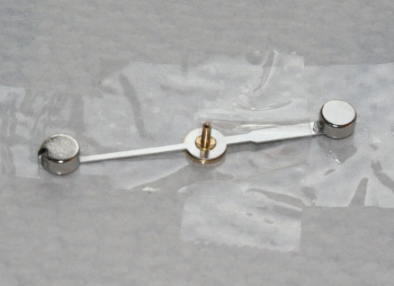 A new clock second hand arm was obtained and modified to support 2 magnets. The long arm shortened to make both ends were the same length and a magnet was glued to each end, carefully measuring exact same distance from the center.
This resulted in 2 'on' triggers per minute. This had to be matched with a second trigger (2nd magnet) fitted to the drive wheel. As a result, the stop/start system operated twice a minute and this allowed the max. error to be halved, from 6 seconds per min. to 3 in 30s.
In other words, the waiting time is split into 2 steps. The first 3 seconds at the half way point and a further 3 seconds at the end. Whilst the total is the same, the maximum inaccuracy is now only 3 seconds.
Note - the clock second arm is aluminium and thus non-magnetic. The difference in thickness of the two ends thus has no effect.
How to further increase the accuracy ?
From the chart, a 1 second max stop time would allow the Canon 75-300 to be used at any declination and even allow a 500mm telephoto to be used at Declinations of about 45 degrees and above.
To achieve this, with a 10% speed margin, means splitting the turn into 10 second intervals.
Unfortunately, experience had already shown that it is extremely difficult to align two separate magnets on the drive wheel to a single reed switch with any accuracy .. too close and the 'over-run' required was excessive - too far and the reed switch does not 'trigger' reliably - and then the magnet shifts again as the glue sets. After a number of failures, the idea of adding even more magnets to the drive pulley wheel was abandoned.
Plainly to go further the drive wheel magnets (and reed switches) have to be eliminated altogether.
A 'scrap' micro-switch with a long actuating arm was found. It was decided that six actuating 'cams' should be added to the outer rim of the drive wheel and each arranged to trigger the micro switch, thus generating 6 'Motor Off' signals per full revolution. The same (diode bypass) 'over-run' system was used, so the micro switch arm was positioned to 'turn off' quickly after being actuated.
Note - consideration has to be given to how the system will be 'rewound' back to the fully closed position. The micro-switch actuating arm/cam system needs to be arranged such that the drive wheel can be reversed.
The clock system then needs to generate 6 similar 'Motor On' triggers (one every 10 seconds).
However, to generate a 6 per rev. 'Motor On' triggers from the clock proved to be more difficult. My first attempt was to add a thin plastic 'disc' to the clock second hand and use this to mount 6 magnets. Although the disc was made quite large, the magnetic fields overlapped and it was very hard to arrange the reed switch to 'turn off'.
Whilst this was 'solved' by mounting the magnets around the disc with alternating N-S, S-N orientation, unfortunately, the disc plus magnets proved too heavy for the clock to drive reliably.
Consideration was then given to fitting 6 separate reed switches below the sweep of the original (single magnet) second hand - however it would obviously be very difficult to align all 6 with any accuracy.
I eventually returned to the 'dual magnet' (balanced) second hand together with 3 evenly spaced reed switches arranged in a equilateral triangle formation.
The relay used is capable of switching at sub-second intervals - so the same relay logic was (i.e. the Clock '10 second' trigger is wired to 'Motor On' and the Motor drive micro switch trigger is wired to 'Motor Off' via the diode over-run.
If the Motor is left set to the "10% faster" (i.e. 66 rpm), then the max. error is now 10% of 1/6th of a rev. i.e. 1/10th of 10 seconds = 1 second or 1/60th of a turn, 6x better than before, and we thus achieve a guaranteed accuracy at least as good as that achieved by best manual operation.
What are the practical considerations ?
1) The clock mechanism should not be mounted on the (angled) Barn Door movable arm. Doing so would mean that the (magnet weighted) second hand has to climb 'uphill' half the time - with the possibility that some seconds may be 'missed'. Instead it should be positioned on the (Spirit Level adjusted) flat base.
2) To obtain 6 'On' triggers, with 2 magnets, requires 3 reed switches. These have to be positioned at the apex's of an exact equilateral triangle on which the clock then has to be 'centred'. The triangle requires careful laying out (easy with a compass), however it is then a relatively simple process to ensure all 3 switches are the (exact) same distance from the centre
See http://en.wikipedia.org/wiki/Equilateral_triangle
To keep within the 10% target per 1/6 turn error means positioning magnets and setting reed switches to operate within much less than 6 degrees of arc (1/6 th rev = 60 degrees, 10% of this is 6 degrees). If build accuracy is (say) 3 degrees, this leaves only 3 degrees for Motor speed errors.
That's all for the electro-mechanical drive - for something a bit more 'digital', click "Next>>" (nav. bar, left) ...