

What's it for ?
Like many people I have multiple computers with 6 channel audio output intended to drive 5.1 'surround sound' speaker systems - and no wish (or space) to position multiple sets of speakers around the room. It also makes no sense to drive more than one set of speakers 'at the same time' - so there is just no point in having more than one 'set' in the same room anyway. Unfortunately, there appears to be no such thing as a '5.1 speaker switch' = so I decided to build my own !
More modern computers come with HDMI output, which is fine if you have a home cinema 'decoder amplifier' that accepts HDMI input (or use a HD TV with built in Surround Sound as your 'monitor'), since HDMI switches are easy to find.
What's needed ?
Each computer has a set of 3.5mm 2 channel ('stereo') jack sockets, which output the decoded 5.1 channels arranged in pairs using 3 'stereo' cables (as "front left + right", "center + LFE" and "rear left + right"). So we need to 'switch' all 6 of these channels together
Some computers have an optical (TOS) or 'video' co-ax (RCA) S/PDIF output. This carries encoded audio (either Dolby Prologic II 2 channel PCM 'packed' 5.1 or Dolby Digital 5.1 encoded AC-3). However Computer speaker sets are too 'dumb' to unpack or decode the 5.1 from this source, although your Home Cinema may have a Optical (TOS) or co-ax S/PDIF input - in which case go for that (both optical switches and co-ax switches are easy to fine, as are TOS <> co-ax 'adapters')
The 3.5mm sockets at the computer make the usual poor connection with the actual cables, but there is no getting around that since they will be built into the PC motherboard. However it's quite possible to use RCA 'Phono' co-ax sockets on your switch box (by using '3.5mm jack to RCA plug' cables). You need 3 cables per computer, so 6 for a '2 way' switch
The signals will be decoded PCM digital 'pulse trains' - so, in theory, noise should not be a problem, even if you neglect to 'earth' everything
The switch output will have to be 3.5mm sockets - unless you are very lucky and your speaker system comes with separate cables (in which case I recommend going for RCA on the outputs as well). Needless to say, The Dell system has all 3 cables wired straight into the 'sub-woofer'
In addition to the sockets, you need some sort of actual signal switch - ideally a '6 pole 2 way' rotary switch - unfortunately, despite some searching at 'the usual suspects' (CPC, Maplin and eBay) there appears to be no such thing as a '6 pole 2 way' rotary switch (at least not at any sane price)
What I used instead of a 6pole 2way switch
I've seem some designs that use a set of 3 '2pole 2way' switches - however this is rather 'inelegant' - so I quickly hit on the idea of using relays. The drawback is, of course, that with 'normal' relays, the contacts 'default' to one position when the 'power is off' and if you want the other position you have to keep the 'power on'.
Another choice would be some sort of semi-conductor 'switch' - the only problem being the power issue (you would have to provide a 3.3v or 5v 'stabilised' power source to run the electronics)
Fortunately, I remembered the box of 3v 'latching relays' (type DK-1a1b-L2 3v) I purchased for my 'Barn Door' / "star-tracking" project. These wonderful little units have internal 'magnets' that 'hold' the relay contacts in position i.e. the relay contacts can be driven into position by a 'pulse' of power since, when the power is removed, the contacts remain in the last set position !
The relay has two switch 'coils' inside - you just have to apply momentary power (eg. via a push button switch from a 3v battery) to one coil and the contacts 'click over' to the 'activated' coil position. They then remain in that position until power is applied to the other coil. This means you can build a battery operated switch that only uses power when one of the push buttons is pressed !
How the relays are wired up
 Note: view is from the pins side
The relay pins are on a .1" 'grid', however the width is .5" (5 x .1") rather than the 'standard IC' .4". Even so, the relay will fit into a 'wide set' 16pin 'IC Socket' or can be soldered direct to standard 0.1" 'vero-board' 8 x 5 hole area
Pin 5 is wired to pin 12 and becomes 'audio out'. The two 'audio inputs' are Pin 8 and Pin 9. As pin 1 is wired to 'ground' and +3v power is applied to pin 16, 'audio input' pin 8 is connected to audio output' pin 5 (and pin 9 is disconnected from 12). If power is applied to pin 15, 'audio input' pin 9 is connected to 12 (and 8 disconnected from 5). All the other pins are unused (actually, missing)
This means that the 2 audio 'inputs' are at one end of the relay and the 2 'selection' pins are at the other end (and the 'output' is taken from the 'middle'). If the computer 'inputs' are arranged along the same width as the circuit board, there will be no need (or room) for a 'screen' connection
The wiring diagram (per channel)
The wiring of a single relay (pins side) is shown - this is duplicated for the other 5 channels.
Note the LEDs = the idea here is just to indicate when the battery is 'dead' - note also the 'reverse protection' diodes (only really needed if you fit the LEDs)
Later (see 'What I would do different') it was realised that the unit really needed to be controlled 'remotely' (cabled to a simple 'momentary action' rocker switch). The 'circuit' is shown here but was not part of the build you see below
Planned mechanical layout
My final layout, view from the 'component' (top) side. My first idea was to mount everything, including the wire links to the 'channel' sockets, on the 'component' side - however this would mean allocating 'holes' for the wires to feed through to the relay pins on the track side. To save a lot of extra track 'cuts', I decided to wire both the input and output wires direct to the track side (the inputs went direct to the same hole as the relay pins, the outputs came from a hole between the two relay 'pole' pins in the middle of the relay position)
Each 'channel' has it's own relay (6 channels = 6 relays). The RCA Phono socket input channels will be arranged as 2 rows across the long side of the box, so each relay can 'pick up' it's two inputs (one above the other - one is shown as red, the other green).
The output 3.4mm sockets are on the other long side of the box, and each socket picks up 2 channels (from adjacent relays) - in this case I've shown each one as a co-ax cable (red jacket, green signal, earthed at the relay board).
The initial plan called for the 'activate' push buttons to be mounted on the same side of the unit as the inputs i.e. at the end of it's respective input row (in 'position 7'). Space was to be left for the LEDs to be mounted next to the push buttons (in 'position 8')
Each relay consists of 5 'holes' plus 1 hole each side - so the minimum 'vero-board' size is 6 x 7 = 42 holes (plus two 'half holes', one at the start and end). I also needed some space at one end for the 'Select' and Gnd wire connections, giving a width of about 4.5" = 115mm. The board was 10 'holes' (+ 2 halves) deep (1.1") or about 25mm. You need to allow at least 20mm all the way around the vero-board for the connector sockets, switches and battery box, so minimum box width will be about about 65 mm (which just allows a 2 x AA cell battery holder (57x30x15mm) to fit in nicely at one end)
Finding a box
The Vero board sets the (minimum) internal width to about 65mm and length to 115+30 = 145mm. But what about the height ? Well, the relays are about 10mm high and, after adding at least another 10mm for socket, vero-board (and mounting) this gives us a height of at least 20mm. If 2.5mm is allowed for the thickness of the case, the ideal box will be about 150 x 70 x 25 mm
I soon discovered that 'Project Boxes' cost an arm & a leg (especially aluminium ones). It also turns out that most boxes that are 150mm long are 50mm or more high, so keeping the height down means dropping the length. I ended up selecting an ABS box from CPC (part EN82869 - 120 x 65 x 40) this is a bit short, but the height would allow the battery holder to be stuck to the lid.
ABS is non-conductive, but I expected that all the internal connections would be short enough to minimise any 'noise' pick-up (remember - the signal will be digital PCM pulse trains, so it should be virtually immune to audio noise) - even so, my "anti-noise 'plan B'" is to always glue some aluminium foil to the insides of the box. Needless to say, when I went back on-line to buy it, it was 'out of stock' !!
Despite their prices**, I went back to the Maplins web site - and after hours struggling with their hopeless layout (you have to open up the individual 'details' of one box after another to discover it's dimensions - plainly the size is not something that Maplins thinks is needed in the short description), I eventually managed to find the ideal aluminium box (part no. LF08J, 133 x 70 x 38) for not much more than my 'first choice' ABS one from CPC ! .. plus, wonder of wonders, they actually had it in stock !!
** I no longer buy components from Maplin as their prices are generally at least double what you might pay at CPC or on eBay. In fact (so long as your order qualifies for 'free postage'), CPC often works out a bit cheaper than eBay (plus you generally get it 'next day', not next month) !
The actual build
1. The box
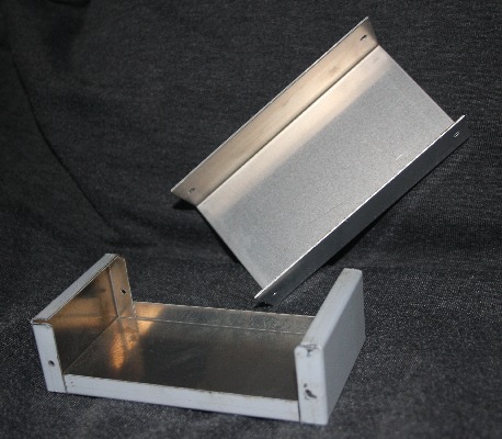
The whole layout is governed by the box. The long sides of the project box are part of the box lid. So, after the RCA socket wires are wired to the track side of the circuit board it will no longer be possible to get access to the 'component' side.
This means that all the 'component side' items will have to be be soldered in first (i.e. the wire link and the relays, not forgetting to 'bend pin 16 to the top 'Select 1' track). I then added some 'flying leads' for the GND, Select 1 and Select 2 control switches. With these 'reference points' in place, the vero-board track 'cuts' can be made (I used a hand-tool - essentially a 2mm drill with a handle - to 'grind off' the track at the holes where the 'cuts' were required).
2. Relay board
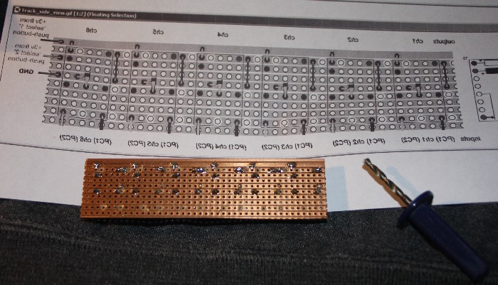
Having done the basic vero-board wiring up, the next step was to make all the 'cuts' on the track side (and then make sure the relays were actually working, both 'switch over' and 'hold').
Note the 'track cut' diagram - yep, it's the original plan 'mirror imaged' for track side view (it's way too easy to cut the wrong track if you work from the 'component side view' :-)
It was at this stage that I decided to leave out the LEDs - six relays switching at the same time made such a nice loud 'click' that there could be no doubt they were working !
3. Drilling the 'lid'
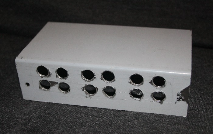
When I came to drill the RCA socket and switch holes all in the same side, it became obvious that there really wasn't enough room to fit it them in. I thus decided to move the switches onto one of the 'short' sides in the base.
You will note that the shite/grey protective plastic covering is starting to come away at the edges - this is due to my over-enthusiastic filing down of the 'burrs' left over from the drilling (that's what you get if you use blunt drills :-) ).
The short side is where the socket for the 'remote control' cable (see later) would go
4. The sockets
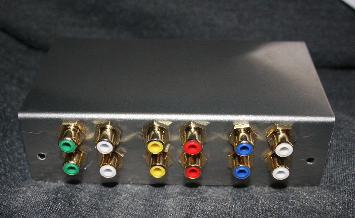
On the back of a computer with 5.1 output you will find the 3 sockets - Front L/R (Green), LFE/Cntr (Yellow), Rear L/R (Black). The speaker system (sub-woofer) has 3 cables with coloured plugs - 'Beige' (a sort of off-green), Yellow and Black
I decided to do the same, but, of course, needed two RCA sockets for each stereo 3.5mm to RCA cable. The 'tip' pin was 'white', so I coloured this. The 'middle' pin was tagged with a red band, however since the 'yellow' was hard to see, I decided I would only keep the 'red band' on the yellow cable (and use a red socket), whilst removing the red band from the green & black cables (and use white sockets).
Since the 'black' RCA socket was 'out of stock', I purchased blue instead. You can see the result, left.
5. Wiring and assembly
So long as the input 'pairs' are wired correctly to the output sockets (i.e. centre pin to centre pin) the actual speaker (left or right) doesn't really matter (until one speaker stops working :-) )
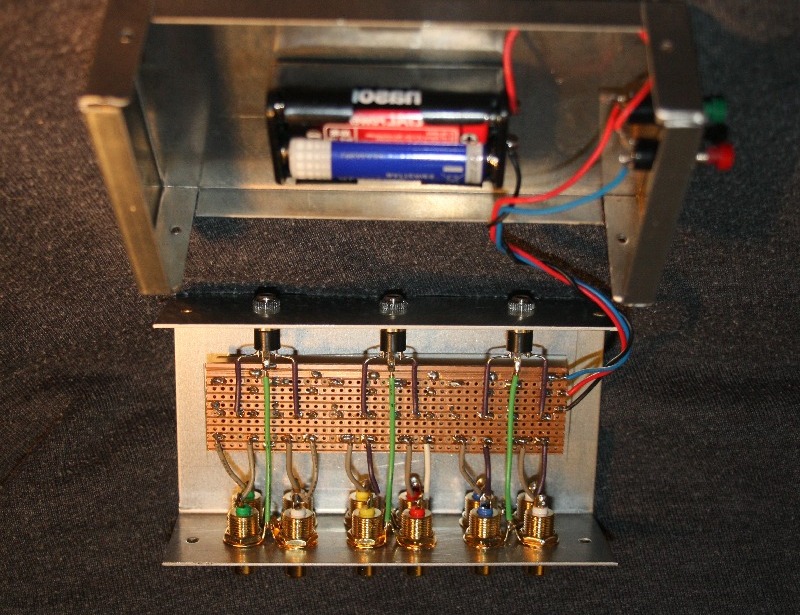
There would be so many wires holding the board in position that adding 'mounting' bolts seemed pointless. Instead I just used 'double sided tape' to stick the circuit board to the 'lid' before wiring up (and used the same to stick the battery box to the base)
The photo has been 'flipped' so it aligns with the others (i.e. sockets at the front) which is why it looks a bit odd.
6. The finished 6 CH (5.1) switch unit
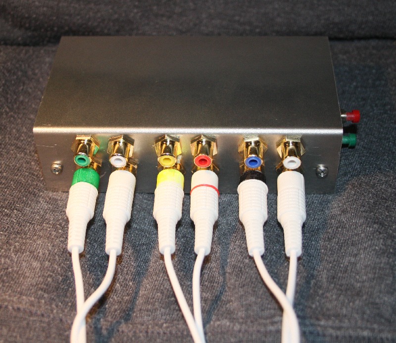
Left is the finished switch. Note how the cables are coloured to match the sockets (mentioned in 4 above) - the 3.5mm plug ends (at the computer) were also marked (Green/Yellow/Black)
Wrap up - what would I do different next time ?
Cable runs and socket positions
The socket layout is not actually 'optimum' for running cables from 2 computers. With two computers quite close together, the obvious place for the switch would be positioned at the back / top of one, with the RCA inputs 'naturally' facing toward the 5.1 outputs on the back of the computers. Of course, this would make the push-buttons very hard to reach.
Worse, the 3.5mm outputs then end up 'facing the front' requiring cables to 'run over the top' (to reach the speaker sub-woofer unit which is likely 'behind' the computers)
Of course there will never be enough room on a small box for all the connectors to be facing the same way, so, as a compromise, I would position one set of RCA inputs on each 'long side' (so 'aimed' at one computer 'on the left' and the other 'on the right'). This allows the 'back' (a short side) to be used for the output sockets with the controls 'on the front' (the other short side)
Remote control
I wouldn't bother with 'select' switches 'on the box', instead I would just fit a socket to support a 'remote control' rocker switch. This would allow the switch to be positioned behind the two computers (and thus shorter 5.1 cables runs).
With the control switch now 'remote' from the unit, I would add the LEDS to the 'top' of the box (so they would be visible even with the switch placed on the floor)
What's it all cost ?
All the components (less the relays) came to about £25. If I had to buy the relays, they would cost well over £5 each, more than doubling the cost !
.. so if you are building your own, I suggest spending a little more time than I did searching for a 6pole 2way (rotary) switch :-)
Click 'Next >>' in the Navigation Bar (left) for my next topic