

What's a 'ring flash' lamp (LED ring-light) ?
This is a LED based lamp that fits around the front of the camera lens to illuminate an object for 'Macro' (very close-up) photography. It's needed because the camera's own built in flash can't reach anything very close to the lens without casting shadows (the lens** itself gets in the way and fancy fibre-optic 'light pipes' that redirect the light from the flash past the lens typically cost more than a separate flash unit).
In the old film days, a 'ring flash' was exactly that - a ring shaped flash tube - however with the increased sensitivity of digital camera's it's now possible to use LED's in an 'always on' mode (which makes focusing a lot easier :-) ).If extra light is needed during the actual exposure, LED's can be driven for a short time (mS) at much higher currents (typically 5 to 10 times higher) so long as they are given time to cool down before being called upon to 'flash' again. The design chosen below uses two sets of batteries to drive two sets of LEDS, thus allowing future addition of a 'sync' driven 'switch' flash capable of placing up to double the normal voltage across the LEDS
** A macro lens is a big chunky thing typically up to 300mm long. A 'DIY' macro lens 'assembly' (= a standard lens with spacer ring(s) that has been 'reversed') can be even larger
Any lens that is 'reverse mounted' can only be used in full manual mode, allowing almost any ancient 'film camera' lens (or an 'enlarger' lens from an old darkroom projector) to be pressed into service. There is, however, one slight problem with a DIY solution based on a 'modern' lens = a lack of manual aperture control ! A modern Canon lens will be 'stuck open' at max. aperture (i.e. minimiun depth of field), however a Nikon closes down to minimium apeture (which makes them unusable). One solution to the 'stuck wide open' 'problem' is to 'de-glass' a 50mm (or smaller) prime lens from your camera, leaving the aperture blades intact so you can control aperture from the camera - see extreme-macro.co.uk/empty-lens. Since a deglassed lens will act as as the 'spacer ring', if you can 'source' your cameras 'kit' lens (most likly the cheapest option) from eBay, this can work out cheaper than purchasing 'real' spacers !
Why split the LEDS into 2 sets ?
Having the option to illuminate only the left, or only the right 'half' of the subject allows you to create 'shadows' on 'almost flat' objects (such as coins) to bring out the surface details.
What 'mount' approach did you take ?
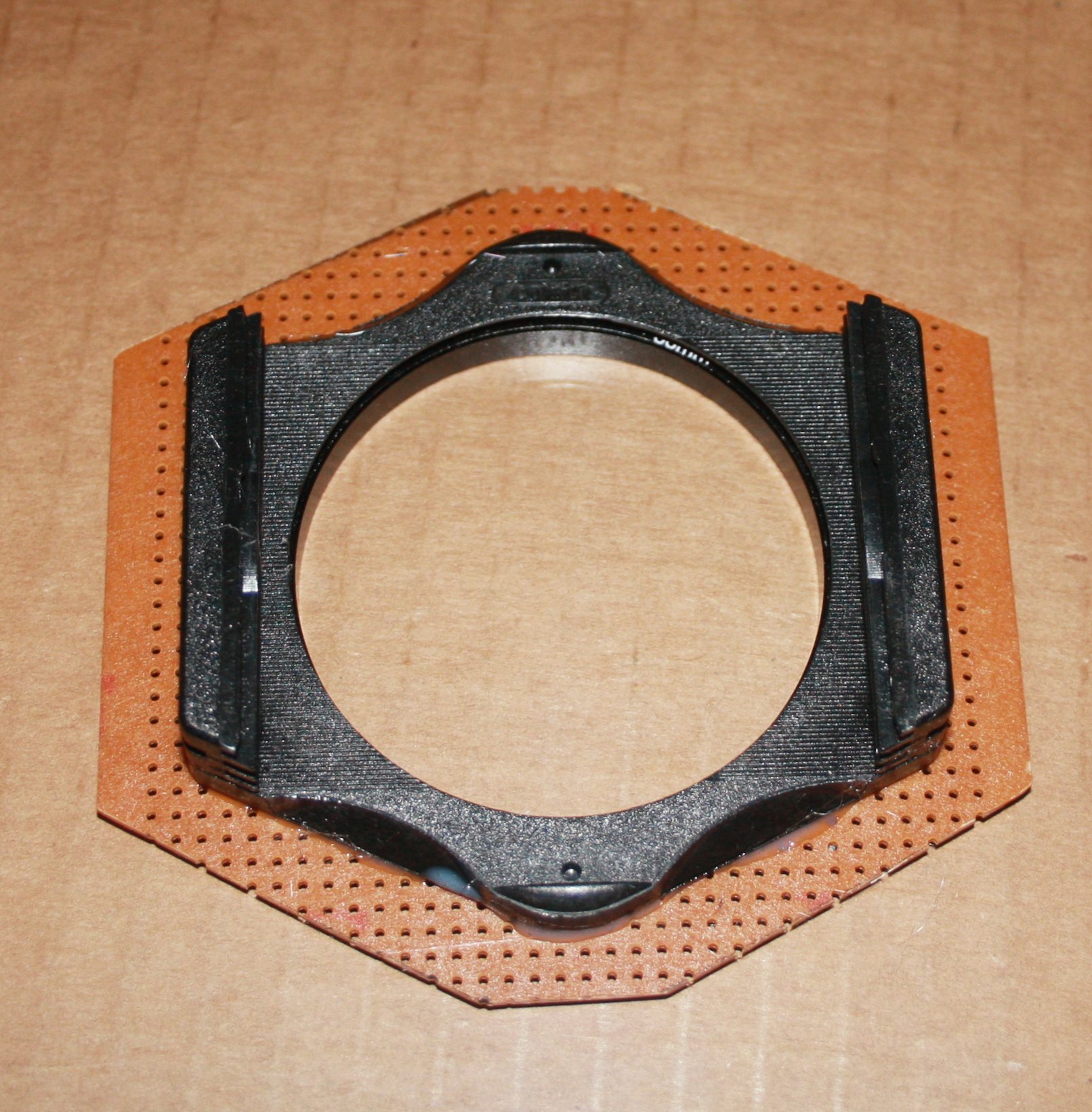
For amximium flexibility, what's needed is something that will screw into the lens 'filter ring' (or the 'spacer ring hood' on the (new) front of a DIY macro (reversed) lens). I started with an old Cokin 'A' series filter mount equipped with a 58mm adapter ring (to suit my lens). I decided to mount the LED's in such a way that it would still be possible to actually add a filter. The PCB carrying the LEDS would thus have to be fitted to the 'back' of the filter holder.
Another goal was that when assembled to the front of the camera lens, it should be possible to rotate the LED light assembly to 'any' angle, thus allowing the 'one side only' illumination to be 'aimed' at any angle required
Can you detail the construction ?
Of course ... (note - to see the image detail, right click and 'view image')
I started with a number of 'high intensity' white LEDS intended to be run from a 4.5v (3 x 1.5v primary batteries) supply via 'drop' resistor. This is ideal, as bypassing the resistor would apply the full voltage allowing a (short) 'flash' to be achieved. Since I already had the manufacturers battery holder attached to the camera, I decided to add a pair of 1x3 AA 'stick' holders that could be 'rubber band' attached to the front of the existing battery holder. Each would have a separate micro-slide switch allowing me to turn on/off the 'left' and 'right' LED sets independently. Such holders cost approx £1 each from eBay.An alternative approach would be to 'hack' a 6 cell AA (2 rows of 3) battery holder to electrically separate the two rows
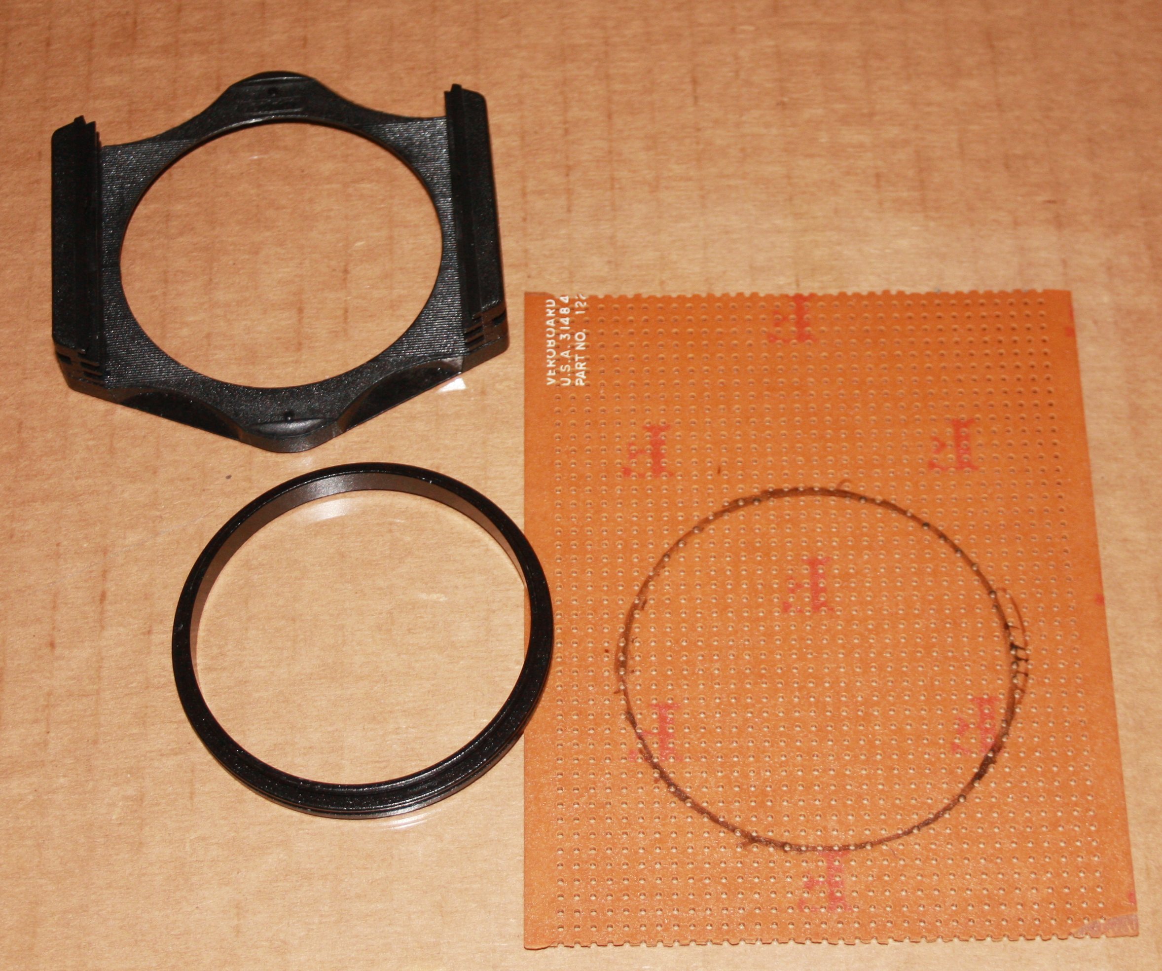
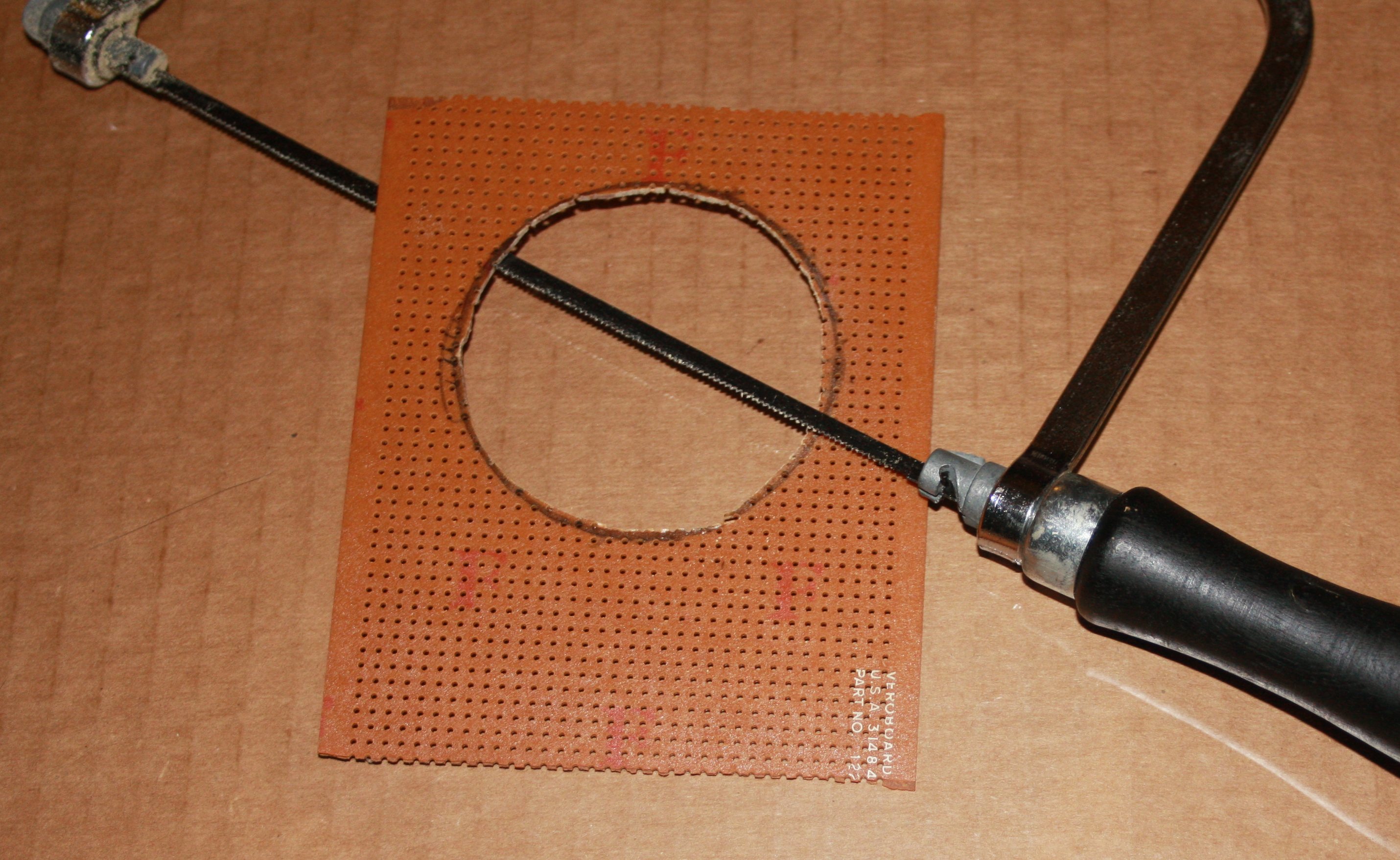
a1. Start with a section of prototyping PCB 'stripboard' and draw around the outside of the 58mm adapter to mark the size of the required cut-out then cut out the center
To make it easier to fit the side LEDS, the stripboard tracks should be 'aligned' vertically = see later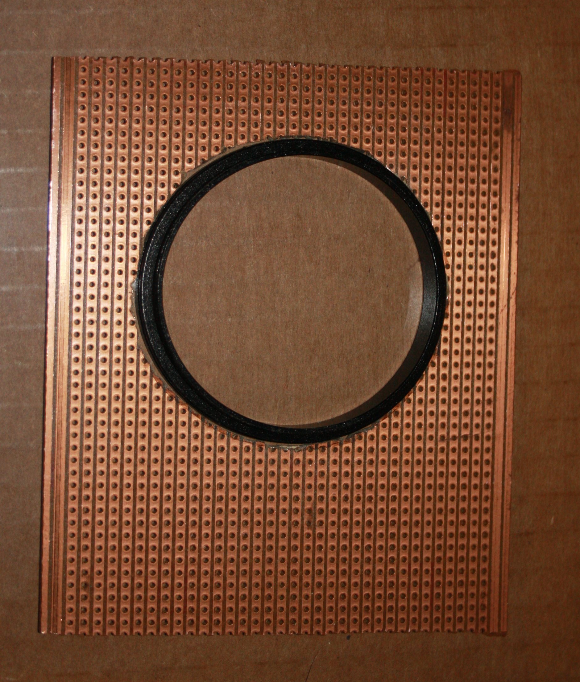
Manually align the filter holder & adapter ring with the PCB, and check it will still screw onto the front of the lens ! - if not, use a half round file to enlarge the hole in the stripboard.
Note the strip board tracks running vertically - this avoids the need to 'wire up' the side mounted LEDS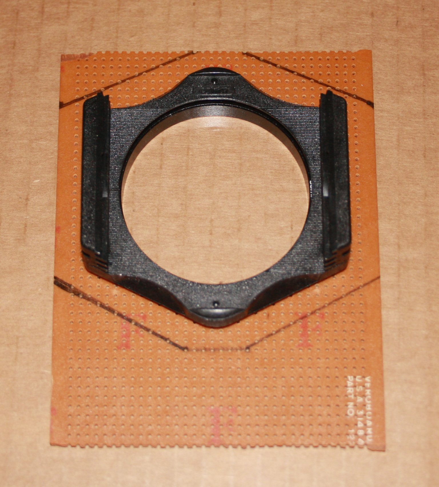
a2. Then mark the edges (left) - you need 3 or 4 stripboard 'holes' clear at the top and bottom of the filter holder to fit the LEDS and wiring - you only need 2 holes at the side (since power will be picked up from the vertical stripboard tracks)
a3. Clean everything using a detergent to 'degrease', and then use an epoxy resin to glue the board to the back of the Cokin filter holder (right). Note that the 58mm ring must be free to move inside the filter holder / PCB assembly (although it will no longer be possible to remove it from the filter holder)
To prevent any epoxy 'sticking' to the adapter ring, I coated it with a fine mist of oil before fitting it back into the filter holder. If you do the same, be aware that it's REALLY difficult to avoid oil getting over the filter holder itself (and then having to clean it again :-) )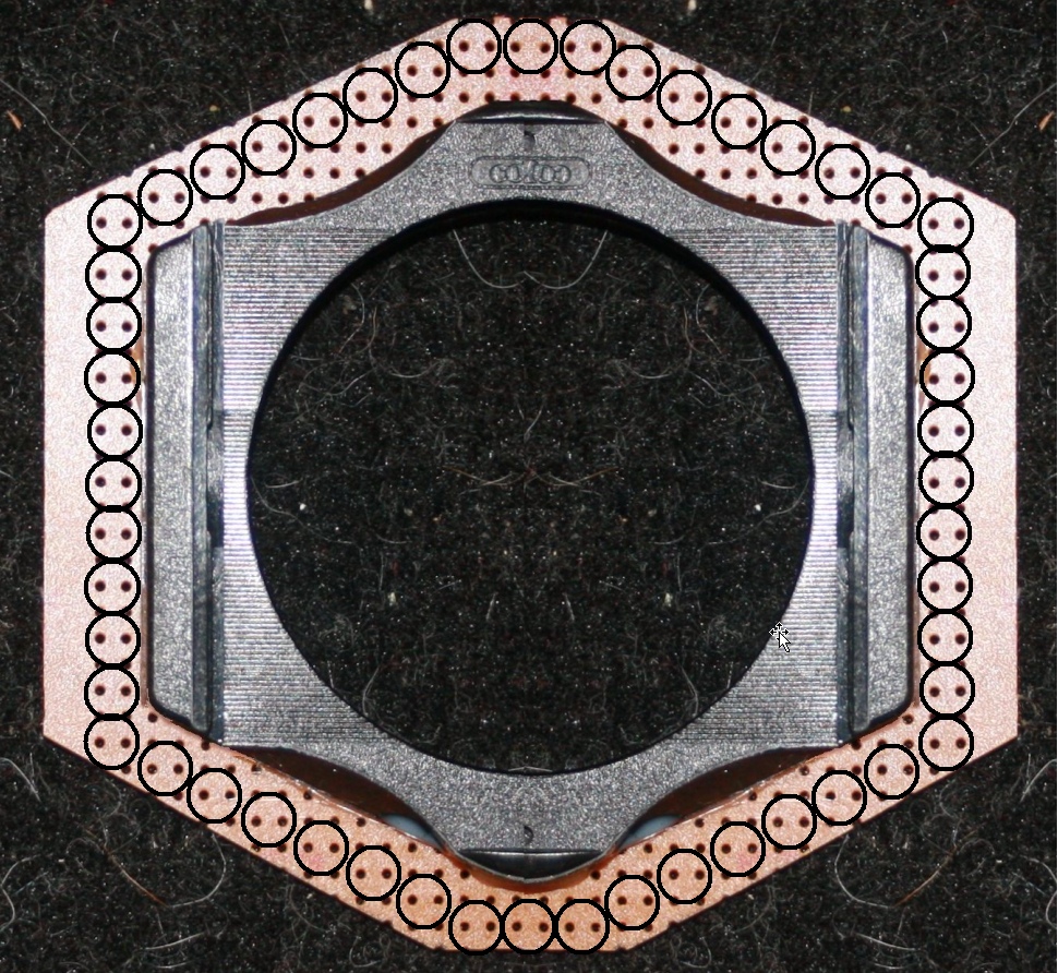
a4. Plan the positions of the LEDS around the edge of the filter holder.
My initial layout (left) showed that 52 LEDS could be fitted, however I only had 32 available - and it was also necessary to leave sufficient space for a power socket and wiring.
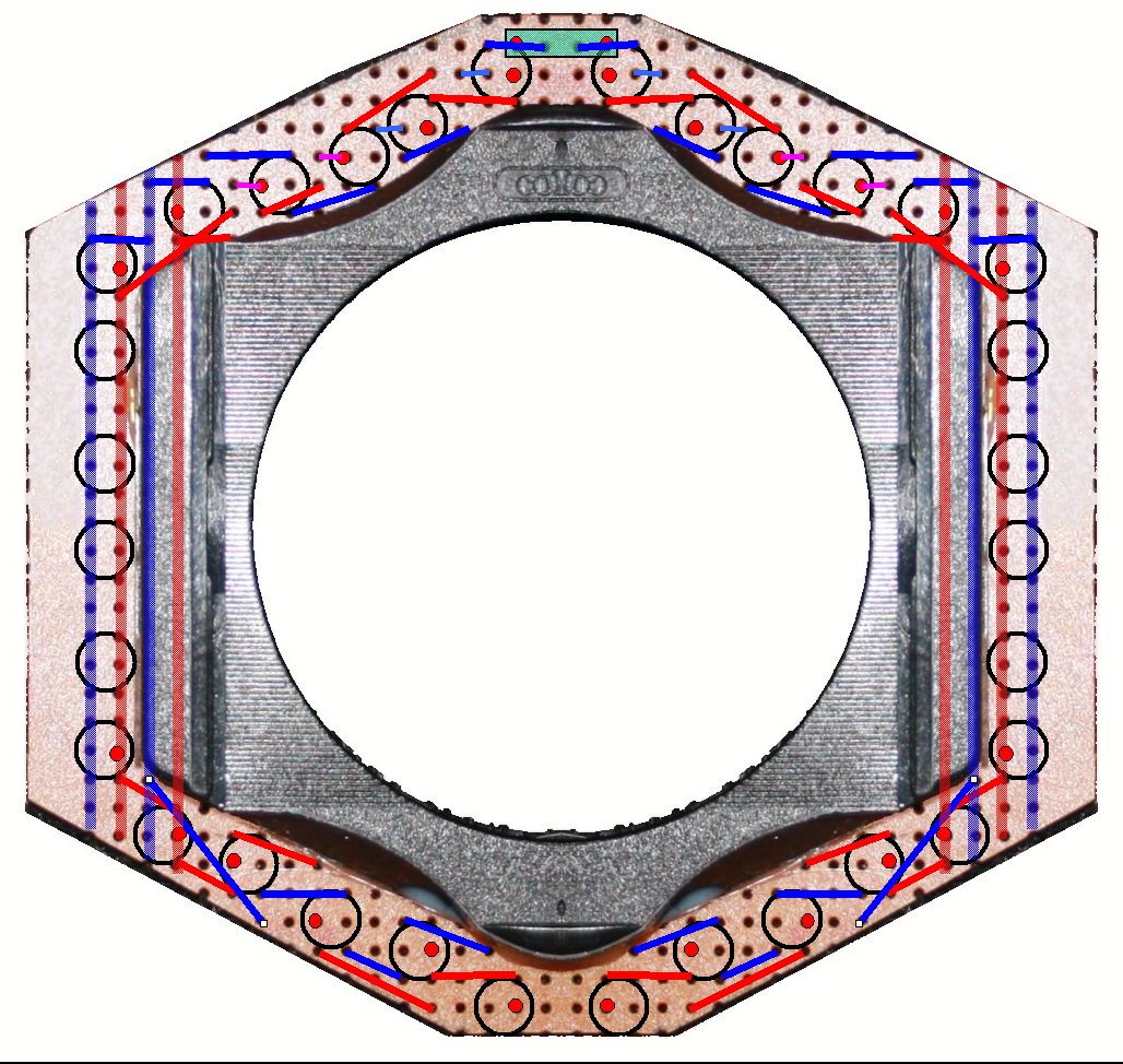
My next plan (right) had space for 32 LEDS and wiring. The translucent green rectangle at the top is the rear mounted power cable socket = this allows the LEDS to be powered in 2 groups (the 'left hand set' and 'right hand set') - if the power plug is inserted 'backwards' by mistake this simply 'swaps' the 2 groups (rather then reversing the polarity & risking damage to the LEDS).
It is only necessary to plan one set of LEDS (the other side being symmetrical). You will note the odd wiring at the bottom left (& right) - the consequence of soldering in LEDS backwards from the first plan :-)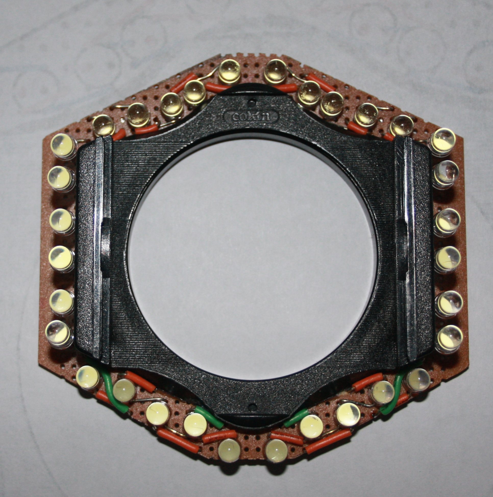
My first assembly. I 'bent' the LEDS slightly 'inward' the idea being to illuminate an object at the minimum focus distance** of my Canon 18-55 lens, which is about 12cm (about 5") in front of the front glass.
After building the first ring light, and turning it on, it was immediately obvious that the LEDS had not been bent 'in' far enough (and the edge of the filter ring prevented any further bending). The result was very 'patchy' illumination around, but not at, the 'focus' point !
**Note, Canon's specification gives the 'Minimum focus distance' as 25cm. As is industry practice, this is measured from the subject to the 'film plane' (i.e. to the back of the camera), not to the front of the lens
The Mk 2 version
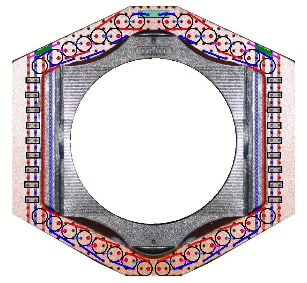 a5. I thus had no choice but to start again. Whilst de-soldering my first attempt, I came across a 9 LED 'head light' at my local 99p Stores and decided to add 2 sets of LEDS from these to the assembly (the in-line resistor for these is shown as a green rectangle at the top left & right of the plan, left - your can click the photo for a more detailed view).
After de-soldering the existing LEDS and making a new layout plan, the first step of the new build was to cut off the 'top' sides of the filter holder (leaving just one position for a single filter glass) so the LED's could be bent in a lot more
Note the LEDS from the 'headlight' are shown as rectangular blocks along each side. This is because they had to be mounted on a 'header strip' to allow alignment - and the best way to align is to solder in the LEDS one a time aligning each as you go along
a6. The final step is to fit the power cable and switches to the battery box and assemble this to the Camera (using rubber bands) and test. Note that having a 'pluggable' power cable makes everything at lot easier to assemble, especially as the ring light assembly has to be screwed into the front of the lens and rotated to the correct orientation :-)
What results did you achieve ?
TBD
Click 'Next >>' in the Navigation Bar (left) for my next project