

The 'hardware'
1) A Pi. Essentially, any Pi = even (in fact especially) the Pi Zero will do the job. You don't need any fancy GUI or even lots of space for images (since it only makes sense to store the 'thumbnail' = display resolution photos. All you need to do is download the basic Jessie/CLI onto a 4Gb SD card
Note that if you develop on a 'normal' Pi it will be harder to move to a Pi Zero (you can't just move the SD card). So if you are going to use a Zero I recommend getting a second one for development (two Pi Zero's, even after paying postage on each, is still cheaper than one A+)
1a) Case One thing to avoid is the official 'Pi Case' = it has way too many holes that just allows dust (and foreign objects) to get whilst providing no support at all for sicket adapters or cables.
Even if you use a single Pi Zero for both development and the 'final project', I recommend you build the Pi into the smallest possible 'Reallu Usefull' box. You only need to cut 3 holes = one for access to the SDHC slot, one to support the HDMI cable (or mini-HDMI to HDMI adapter for the Pi zero) and finally a hole for the power cable
2) A display. Because a mix of portrait and landscape photos looks best on a 4x3 screen (rather than some fancy 16:9 wide-format HD screen) you will likely be using some ancient 4x3 SVGA LCD monitor.
If you use a small low resolution display - eg 640x480 - it won't handle the default 'half HD' video mode (1080x720) used by the Pi at power on, so you won't see the status messages.

To correct this, before moving the Jessie Lite SDHC your have prepared, on your PC open the FAT32 partition and edit the cmdline.txt file using any text editor by adding " video=640x480  " after "rootwait" (the file contains a SINGLE LINE of text)
3) 5v power. Some not-so-old displays come with a built in USB hub which you might think could be used to power a Pi Zero (or Pi A+). Unfortunately, 'Energy Star' compliance usually means the display USB hub won't 'power up' until it detects it's being used (by a USB host, i.e. the Pi) - so you get no power at power-on. Some displays come with DC power out for a 'sound bar' or similar option = these are typically 12v at 1A or more (and most can be set to 'power-on the audio' even when there is no video signal) so all you need is a £1 USB 'car charger' to power the Pi.
If you can't get DC power from the display, you need a USB charger 'power block', ideally one where you can remove the huge UK mains plug (and solder mains power wires direct to the 'tags').
4) Cables and connectors. What you need depends on what type of video input the display has and which Pi you chose. Needless to say, you should ideally go for cables with the 'right' connectors on each end (and avoid using any sort of over priced 'adapter'), however in some cases finding the right cable can be next to impossible.
If the 'old' display has a HDMI socket for video input, that's just fine. For the Pi Zero you need a mini-HDMI to standard HDMI cable (or adapter), for the other Pi's a cable with standard HDMI at both ends.

If the display has DVI (instead of HDMI) you can add a 'HDMI to display DVI' adapter (it being almost impossible to find a mini-HDMI to DVI cable)

Finally, if your display is really ancient all it will have is a VGA socket. The 'neatest' way to link to this is to fit a 'VGA gender changer' to the display socket and then plug the output of a 'HDMI to VGA converter' into that. The cable end of the HDMI to VGA converter needs to be mini-HDMI for the Pi Zero, standard HDMI for other Pi's.
To link the Pi to a display with a USB hub, you will need a cable with a USB 'Type B' (the square' style) socket. The other end will be micro-USB for the Pi Zero, standard USB for others.
Notes.
1) One ideal display is the Dell 2001FP. It has a DVI-D input socket, a built-in 4 port USB hub. The optional 'sound' bar' power socket delivers +12v DC at 1.5A, more than enough to power the Pi (via a £1 'USB car charger' = see below)
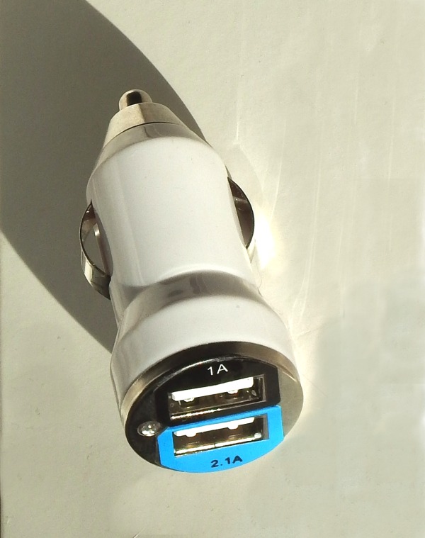
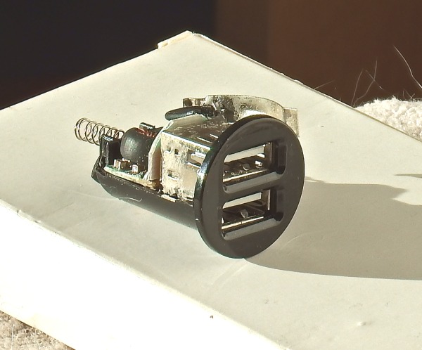
Below left: typical 99p car USB adaptor. Below right: guts of one I dismantled earlier
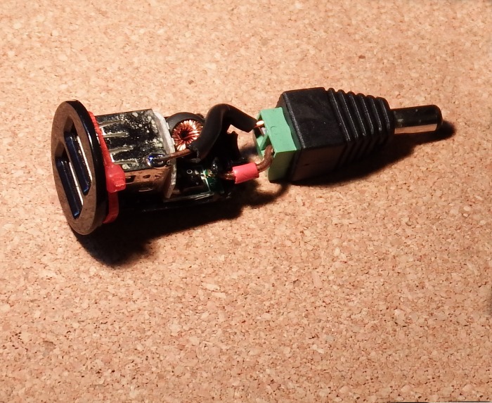
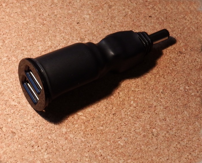
Below left: the guts wired to a 3.5mm power plug. Below right: shrink-tubed and ready for use
2) The smaller RAM on the model A (256Mb) is not a restriction since you will always 'pre-size' the photos to be displayed.

If you want to display photos from a camera chip or USB stick 'plugged into the Pi', the best approach is to have the Pi re-size from USB stick to SDHC card and display only from there.

Images pre-sized for a 1600x1200 display are typically less than 1Mb each. This means a 4Gb SDHC card (which will typically have 3Gb free space) is more than big enough as it will have room for over 3,000 photos !
Building the system
Running a GUI on the Pi is pointless = the GUI will 'take control' of the (photoframe) display and this just makes everything more difficult. Instead I recommend sticking to the CLI.
The 'easy' way to setup the Pi is via a PuTTY terminal window on your PC - which means connecting the Pi to your PC.
Ethernet connection
The easy way to setup a Pi from your PC is via a wired Ethernet connection. Only the B series have an Ethernet socket, but to keep costs down you will want to use a Pi Zero / A+ for the final construction
On a B series Pi, the Ethernet cable just plugs in and the Pi just works.

On the Zero / A+ you can plug in a USB Ethernet 'dongle' and hope for the best = most now work fine.
(an alternative is to use a Pi B series to setup the system and then move the SDHC card to a Zero/A+ during final construction)

NB. For the 'in house' PhotoFrame you are likely to want to keep the PhotoFrame on your LAN so you (or it) can update the photos displayed.

However, for a 'demo' or 'mobile' system', you will likely want the Pi to have access to a USB memory stick (or USB multi-chip reader) so you can load photos from a USB stick or camera card 'in the field'.
Of course if you intend to use the A/A+/Zero with a hub (or the display comes with a hub built-in) you can 'build' the system with both Ethernet and USB access
What about sound ?
Some no-too-old LCD displays have built in speakers, so if you can obtain one, do so (if the display has built-in sound your Pi photo-frame can be used as a 'stand-alone' movie player !)
Having the ability to play music whilst showing your photo collection is also an advantage.

If your display has a HDMI input socket, it will play sound direct from the HDMI data stream.

A non-HDMI display usually supports audio input via a stereo jack socket, which would 'match up nicely' to a Pi A+/B+ stereo output jack (see note), assuming you can get the Pi to separate the audio from the video when using HDMI).

Some non-HDMI displays come with a DVD-D socket, allowing the use of a HDMI-DVI cable/adapter but you need another path for the audio.

Most non-HDMI and DVI displays also have a VGA socket. To drive this, you need is HDMI->VGA Converter and one with an 'audio split off' costs no more than £5 (even from Amazon). This would be the 'only' solution for a Pi Zero and would work also just fine with A+/B+.

Note. The Pi stereo jack output used to suffer from driver induced 'clicks', 'pops' and 'crackles' at the start (and end) of each track, however this was fixed some time ago. Even so, poor power regulation can still cause annoying 'hums' on the A/B, so stick to the A+/B+ (which have a separate on-board power regulator just for the audio out).

The Pi Zero lacks a Stereo output and whilst it is possible to get access to the on-board PWM (using one of the 'alternative pin function maps') and build a 'DIY' version of the audio output circuit, it's not possible to improve on the poor quality '6 bit' sound generated by the other Pi's. If you want audio from the Zero, I recommend the "pHAT DAC" add-on board (a Zero (£4) + pHAT DAC (£12) is still cheaper than an A+ and will delivers far better sound).
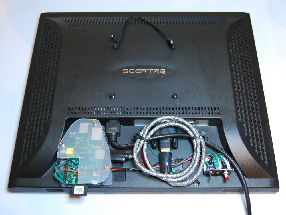
Mounting the Pi onto the display
If you are lucky, there will be room (for example near the cable connections) to mount the Pi within the existing 'depth' or even inside the monitor case. If not, you may need to remove the case and construct some sort of mounting frame.
If it's possible to mount the Pi so a USB socket is 'accessible' to the photoframe user do so - if not, just get a USB-male to USB-female 'extender' cable (the Pi Zero, with it's micro-USB socket, will need a micro-male to USB female 'adapter' cable), so you just need to find a place to glue the USB socket end of the cable. Providing user access to a USB socket will allow them to load photos from a USB memory stick.
When not using the USB socket for loading via memory sticks, you could use it for a USB WiFi adapter, which then allows photos to be 'loaded' via your home network
The A (and B) Pi's suffer from the problem that 'hot plugging' a USB memory stick can 'crash' the Pi (and even corrupt the SD card). To avoid this, use a 5.2v power supply rated at 1A or more (if it is still a problem, add an additional electrolytic capacitor across the USB socket power pins on the Pi PCB (30-50uF @ 6v should do). The A+ is a lot more robust (as well as consuming less power).

To avoid having to 'pull the plug' (and risk corrupting the SD card) to reboot, it's a good ideal to fit a 'Reset' switch. This needs to be easily accessible to anyone plugging in a USB stick (just in case the Pi 'locks up' after all). Needless to say, the photoframe script must 'start' automatically (and scan for a USB device containing photos).

Finally, an 'off' switch is another good idea (as is setting up the Pi to auto-shut down the display overnight = see at end)
Fitting a Reset Switch
WARNING. The 'reset' holes (on the A/B, marked 'P6', at the edge of the board just to the left of the HDMI socket) should be avoided ! This is a 'hard' reset that allows the Pi to be reset when it 'locks up', however if used when the Pi is NOT 'locked up' it can cause SD card corruption !
You need to select one of the GPIO pins and 'monitor' that in software (eg. with a background task (script)). You then need to program the software to issue a 're-boot' command when it 'sees' you have pressed the switch. This is the ONLY way to ensure an 'orderly' shut down and avoid SD card corruption