Powering the Raspberry Pi
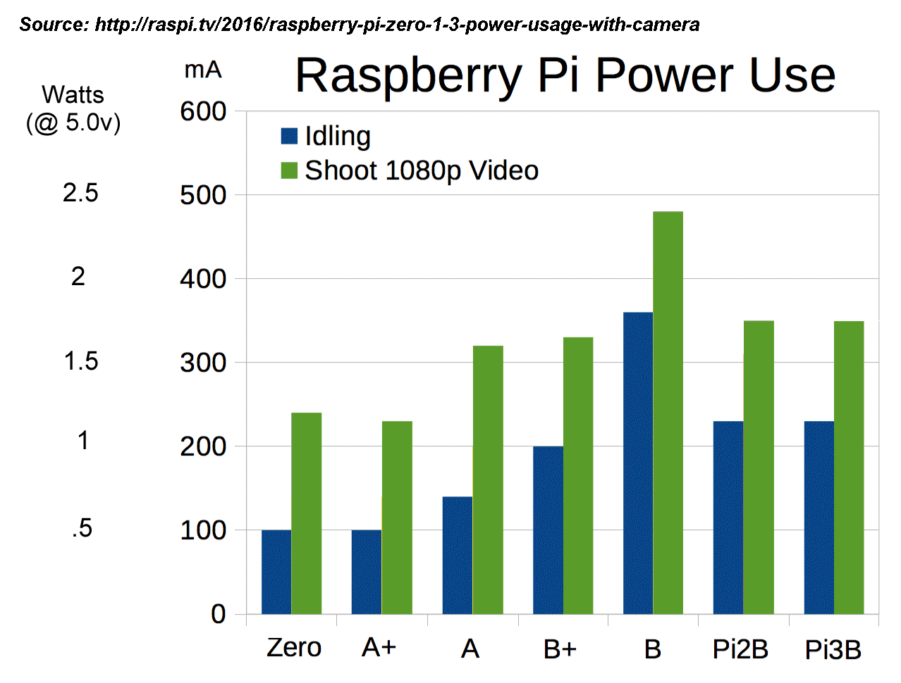
Pi power consumption is actually quite low - from about 100mA (Zero/A+) to about 250mA (modern B series). Even the original Pi B only consumes about 350mA. The camera adds another 100mA to these figures and (for the B series) and you would also have to add any power provided by the Pi to any attached USB devices, however "in theory" all you should need to run the original Pi A or B is the standard 500mA USB charger
However it didn't quite work out that way ...
USB chargers
Despite the low power requirement, when the Pi was first released it was quickly discovered that almost no "500mA" USB charger was capable of maintaining 5.0 volts at 500mA. Indeed, to get anything like 5.0v, you needed a charger rated at 1A. What's more, even some 1A chargers proved unable to regulate their output voltages sufficiently well enough to avoid dropping below 4.75v and causing 'random' Pi resets.
This should not have been surprising as most USB chargers are designed to recharge phones, not cope with the wildly varying demands of the Pi.

Many phone manufacturers, knowing that their phone would cope with anything from 4.5 volts upward, had little incentive to spend money on clever circuits capable of maintaining a steady 5.0 volts from their 'freebie' bundled charger.

About the only 'charger' that would 'do the job' when the Pi was released was the BlackBerry (an early 'smart' phone) charger and those intended for Tablets and eReaders, and, at £10 and up, none of these were 'cheap'.

However manufacturers of 'generic' 1A USB chargers, being unable to 'predict' what voltages were required, typically output a more stable 5.0v (some even 5.2v) at their full rated output current

So, it should be quite possible to use a 'generic' charger rated at 500mA (so long as you are not powering lots of external USB devices from the Pi = i.e. for the Zero, A/A+), however I would recommend adding a decoupling capacitor of 1,000uF/6.3v (or more) across the Pi 5v power rail.
You can now find perfectly good 'generic' 1A chargers that will power the Pi at well under £5 (check out your local Poundland - as of May 2017 they had a 1A rated USB output 'power block' (to which you have to add the cost of a USB to micro-USB cable, for another £1). However, whilst the charger itself might be small, the massive UK mains plug pins makes these less than ideal for building into a project.
To avoid the need to chop off the UK plug pins, look to eBay for 'international' USB chargers, especially those that come with 'mains pin adapters' for various 'mains power' socket types. These can typically be used without any adapter (by soldering direct to the input mains 'lugs')
Note that, since the Pi B3 can actually supply decent current to directly connected USB devices, it is recommended that you use at least a 2A rated USB power supply
'Back-driving' from a USB hub
The Pi Zero, A/A+ have a single USB port and really need to be used with a USB hub - and that hub should have it's own power supply. To avoid the need for a second USB power supply for the Pi, it makes more sense to power the Pi from the hub.
Whilst the B series had more than one USB socket, early Pi's limited their USB output current to about 200mA (only the later B3 Pi was capable of delivering 500mA on it's own USB sockets).

A 4 port hub could (in theory) supply 500mA to each of it's 4 ports - and no Pi is able to deliver the required 2A to that hub without blowing diodes and burning out circuit tracks.

So it's 'recommended' that any hub used with any Pi have it's own PSU, in which case you might as well power the Pi from the hub.

This is known as 'back-driving' and whilst the USB standard requires that 'no USB device shall provide power at any input plug', that's not going to stop the determined hobbyist :-)

A 'real' 4 port hub should have a power supply capable of suppling 500mA to each port. This means it should be rated at 2A, however almost every hub I've ever found with any power supply at all, has one with a measly 500mA rating. Only the (much) more expensive ones come with a 1A supply (and I've never found a 4 port hub with an included 2A supply).

However, there is nothing to stop you buying a cheap hub and cheap 2A 5v PSU and putting the two together, after which it turns out to be quite easy to back-drive the Pi.

NB. try to find a 'generic' hub with a 'power in' socket (it's a lot easier to connect to a socket that already exists and there is at least some chance that the hub PCB tracks will be thick enough to carry the current)
1) The typical hub comes with a standard USB plug on the end of it's 'up link' cable, which is fine for all but the Pi Zero (for which you need a hub with a micro-USB input cable, see (2) below).
To modify the hub, all you need to do is add a wire from the Pi USB cable input '5v' to the hubs +5.0v power socket.
At the Pi end, all you need to do is 'bridge' the Pi's own USB socket 'reverse protection' diode (but only on the USB socket you are going to use with the hub).
2) A hub with a 'micro-USB' plug is ideal for the Pi Zero (but can be used with any Pi**). After making the +5v power wire modification, it can just be plugged straight into the Pi zero USB data socket (the Zero doesn't have any 'reverse protection' diodes as it's designed to be powered from a 'host' computer)
**To use a 'micro-USB' plug hub with other Pi's, the Pi micro-USB power-socket has to be turned into a 'data socket by 'taking over' one of the Pi's full sized USB sockets. To do this, you link 2 small wires from one of the 'full size' USB socket (i.e. link the 2 middle pins (Rx & Tx) from microUSB to a full USB) = and make sure to fit a 'blanking plate' to that socket :-)
With the Pi Zero, you can 'back drive' the Pi from a USB to Ethernet adapter, using PoE (Power over Ethernet) !
The trick is to dismantle a 'micro-USB to Ethernet' dongle and pick up the PoE wires from the Ethernet socket. You then fit it with a 24v DC-DC 5v regulator, the output of which you wire to the micro-USB power pin.

The Ethernet to USB dongle then effectively powers both itself as well as the Pi Zero !
Local Display
Many displays - especially older Dell 'Ultrasharp' range (1905FP, etc) - support a 'sound bar'. This means the display has a DC power output - in the case of the Dell's, it's +12v at 1A
A 'Car cigarette socket USB adapter' can be found that will deliver +5v at 1A for £1 or less (these can sometimes be found in the Poundland stores, although most are 500mA, so check before buying)

It's a simple matter to 'gut' one of these and use it to convert the display +12v into 5v for your Pi.
It's worth noting that many such displays have a built in USB hub (so much the better for a Pi Zero / A/A+), however you can't run the Pi off one of the USB outputs because to get their 'Energy Star' sticker Dell etc. has to disable the USB power out until some 'host' (like the Pi) 'activates' the hub = so you have to power the Pi off the +12v (which can be 'enabled' via the display Menu) before the Pi can use the USB hub.
Power over Ethernet (PoE)
Some projects - especially those using the Pi camera - will likely place the Pi somewhere away from mains power access. Since an Ethernet cable is more or less required (especially if you want a guaranteed connection and high bandwidth (for high quality images)) it makes sense to power the Pi using PoE. If WiFi (or no connection at all) is a better choice, then you will need to look into battery (and solar) power options = see at end below
Once again, it's the Pi Zero, A/A+ that is the easiest to power in this way. They all need a USB hub with Ethernet (and you can 'tap off' the incoming DC within the hub - and even mount the DC converter inside the 'dongle' - and wire up the DC converter output to 'back drive' the Pi from the dongle USB 5v)

The Pi B range is a right pain when it comes to PoE = you have to split off the PoE DC power before the Pi as the Pi Ethernet socket has an internal R-C circuit that will 'inject' any noise on the PoE lines straight into the 100mbs link.
For more on PoE, view the note :-
(+) Power over Ethernet - (PoE)
Battery packs
Remember - in 'sleep' mode a Pi will still consume 30mA (model A), 125mA (B) or 70mA (B+) due to the fact that the Pi SoC does not control power to any of the on-board components (which includes the RAM chip). If you have anything plugged in the Pi USB sockets, these devices will also continue to draw full power. So any application that relies on 'zero' power consumption when the Pi is 'not in use' will need to use some means to physically remove the power (eg a relay)
Warning: Lead-Acid (6v / 12v), NiMH (.12v) and LiPO/LiION batteries all require DIFFERENT charging approaches. In particular, the typical charging method designed for Lead-Acid charging will 'burn out' the other types. The only simple 'universal' approach is to use 'trickle charging' (eg. see Circuit 3, here)
A major complaint from the hobbyist side is that 5v is not exactly 'easy' to get from the 'standard' 6v battery pack (4 x 1.5v primary cells or a sealed lead-acid battery - or even 5 x 1.2v NiMH, which will start above 'nominal' (so '5 x 1.2' NiMH will be more like 5 x 1.3 = 6.5v ..).

You can't just connect 6v (or more) direct to the Pi - if you do, it will, for sure, trip the over-voltage protection 'Zener' (5v rated) and blow the input fuse (6v rated) or you will overheat & blow one or more of the Pi's three on-board (5v to 3.3v etc) voltage regulators.

Standard linear voltage regulators (eg 7805) require at least 7.5v input - and even the 'switching' regulators typically require at least 6.5v (so can't be used to get 5v from 6v, but will work just fine from a 6 cell rechargeable pack = 6x1.2v NiMH = 7.2v)

On the other hand, it appears that you can run the Pi direct from 3 x 1.5v alkaline batteries (nominal 4.5v) or from 4 x 1.2v rechargeable (nominal 4.6v) == but only if you don't try to use any of the USB sockets :-)
With a 6v battery supply, you need a proper 'Low Drop Out' (LDO) regulator, such as this one from Maplin (300mV dropout i.e. 5.3v minimum Vin). Of course you can get the same sort of thing from eBay for a lot less, but be warned = there are lots of eBay sellers who claim 'low drop out' (or even have 'LDO' in their headline description) but then go on to specify 'Vin min 6.5v' :-)
A simple (but risky) 'solution' would be to add a couple (or 3) 'power diodes' in a 6v DC supply before feeding it to the Pi .. at 1A a power diode will drop about 0.3v (so 3 will get the 6v down to 5.1), however the Pi's current demand can vary from less than 250mA to over 700mA (idle with camera to storing photo's on SDHC card) - so the voltage dropped by the power diodes will also vary wildly.
Of course there is nothing to stop you using a higher voltage battery pack with a DC-DC down-converter. Typically these have a 'minimum' input voltage requirement of 6.5v- 7v, so this is not a solution for those wanting to use a 6v battery pack (although a 7.5v, 9v or 12v pack would work just fine)
Finally you can use a lower voltage battery pack with a DC-DC 'up converter' (again, the typical Vdiff will be 1-2v, so in this case for 5v out you need 3-4v in)
Using half the voltage means drawing double the current - so a 3v battery pack will only last for half the time
NiMH rechargeable
It's well known that you can often 'get away with' running 5v kit on 4 x NiMH '1.2v' rechargeable batteries (giving you a 'nominal' 4.8v). It's also (quite) well known that each NiMH, when 'freshly charged', will deliver 1.35v or even more (so 4 x 1.35 = 5.4 v !) and will continue to deliver over 1.2v for at least the first 20% of their capacity (most only get below 1.2v at the "50% discharged" point = see here).
Since the Pi 'minimum' is 4.75v, some enterprising chaps have actually managed to get this to work = although it's to be noted that this was a 'robot' controlled via Pi I/O pins and not something that tried to use any of the Pi's USB sockets :-)
NB. CPC (and some others, eg Maplin) offer a "joke" 'Uninterruptible Power Supply' (UPS) 'Hat' for the Pi using 6x standard (i.e. not rechargeable) AA batteries (9v) for £26 ('batteries not included' :-) )

For less than half that price it's quite possible to build your own real (i.e. rechargeable) UPS 'batteries included' :-) (see my Pi UPS Project)

Note that one problem with the DIY NiMH UPS solution is the 'charger' circuit. NiMH cells can be 'trickle charged' (at constant current - 1/40th the amp-Hr rating of the cell (c/40) - eg using a LM317) indefinitely, however if the cells are exhausted (eg after a power cut), you might want them to charge in less than the 40 Hrs (almost 2 days) that a 'trickle charger' would take (so you can be ready for the next power cut, which is bound to occur sooner than that :-) ). One way to solve this would be to program up a PIC chip to control a 'fast charging' circuit (but that's another project :-) ). The other solution is to use a Power Bank with 'pass-through' charging (see below)
LiPo Power Bank
During the last couple of years, the 'Power Bank' recharger has become quite common and, with prices more than halving in the last few months, is now quite affordable** (although some sellers still think they can rip-off the uninformed punter for upward of £100)
**You can find any number of Power Banks for under £15 in the UK High Street. Both Amazon and UK eBay sellers are even cheaper, with 'rock bottom' prices available from China (when aimed at the smart phone user = replacement LiPo battery packs and packs aimed at the 'model' market (especially model aircraft) are still way too expensive) and watch out for the sellers who offer the case only, without batteries, in an effort to grab the 'lowest price' point !

For the real 'rock bottom' price, go to Poundland, where a single PiPO Powerbank could be found during Q1 2017.
Power Banks contain one or more Lithium Polymer 3.7v** batteries with 5v circuitry allowing the Power Bank to charge phones and tablets (and, of course, allowing the phone charger to recharge the Power Bank)
** LiPo batteries vary from about 4.2v when fully charged to 3.65v when discharged to below 10%. A single cell 'Power Bank' case only, with built in 5v DC-DC converter, is so cheap (99p) that there is just no point in using the 'raw' battery

The standard LiPo '18650' cell power rating depends on how far (how low) the DC-DC converter can 'discharge' the cell. A 'conservative' rating would be 2000-2200 mA-Hr (although some sellers claim up to 2800mA-Hr !). To 'up' the capacity, multiple cells are used in parallel.

Note that the 'headline' 2000 mA Hr etc. capacities are given in terms of the LiPo (3.7v) capacity. The 'actual' capacity (at 5v output) will be 5/3.7 of the headline figure, and the 'real world' or 'in use' capacity is typically about half the headline value (there will be some losses and because recharging a totally flat LiPo is 'challenging', few systems will no discharge the battery much below 10%)

Most cheap Power Banks have simple DC-DC 'dual mode' converters - which can only be used 'one way at a time' (i.e to deliver power to external USB devices or to recharge the Power Bank). If you search around you can find some Power Banks with 'pass-through' or 'charge-through' capability (some call this 'load sharing' or use their own fancy name - like 'Duo-Charge' (Tecknet BlueTek iEP390** / iEP360-W) or 'Smart Charge' (Energizer UE2601, although other manufacturers use 'smart charge' to mean 'fast charge' not pass-through)). These let you both recharge the Power Bank and pass power to the USB output(s) at the same time.

A Power Bank with a 'pass-though' capability means a Power Bank that can be used as a UPS !

In fact, by adding your own 'switch over' circuit (even a single diode circuit can often 'do the job') you can use a cheap non-'pass-through' Powerbank.

** Note, I use the Tecknet BlueTek iEP390 as a UPS for my Pi and it works just fine. You will need to check out any of the others I've mentioned yourself = Power Banks are designed as phone rechargers and some (especially older) designs can 'glitch' when the USB power input plug is removed and the unit has to switch over to battery power. Indeed, some older ones with buttons would actually 'auto-off' and wait for the user to press the switch before switching to battery mode !

The Pi Zero with camera will typically run for 5 Hrs from a single cell LiPo '2200 mAHr' Power Bank "UPS".
(-) Power Bank pass through
How 'pass-through' works
Loads of nonsense is written about 'wearing out the battery by constantly charging and discharging it at the same time', mainly by 'reporters' with little or no scientific education.
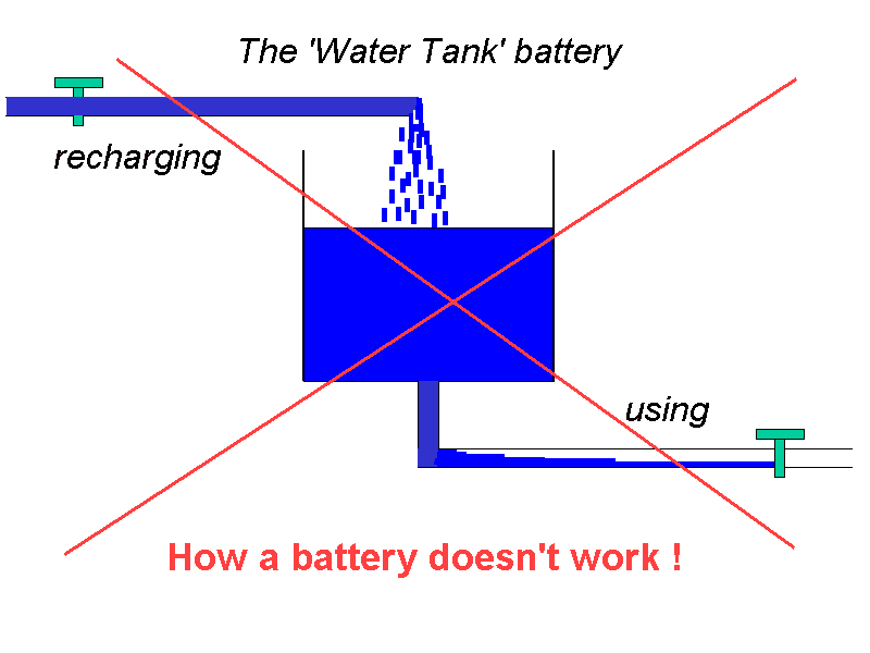
The usual way to explain how the magic of electricity 'works' is by analogy to a plumbing system. However it WRONG to think of a battery as simple open top 'water tank' (with a hole in the bottom out of which power can flow).
It's this incorrect model that leads to the nonsense idea that 'simultaneous charge and discharge wears out the battery' (as you pour water at the top whilst water flows out of the bottom)
This is NOT how a battery works. Instead it's more like the 'expansion tank' you have in a modern central heating system. There is just one 'hole in the bottom' through which power flows in or out (so it's not possible for power to flow in both directions 'at the same time').
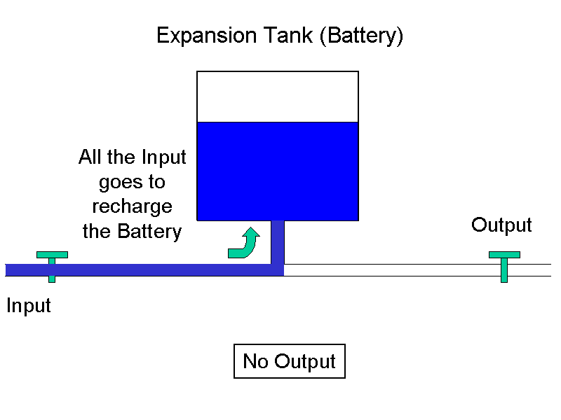
To fill (charge up) the 'expansion tank' (battery), the water pressure (voltage) at the input has to be higher than the pressure already in the tank.
When there is no output, all the input goes into filling the tank until the pressure of the tank (battery voltage) matches the input pressure (input voltage) and the tank (battery) is full.
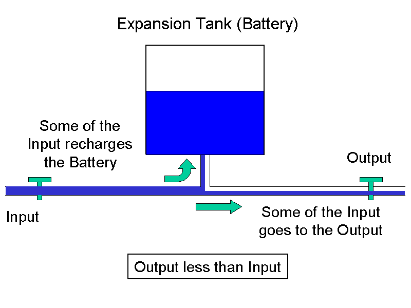
What happens if we turn on the output ?
Well, then some of the input has to go to the output, but so long as the output is less than the input, the 'left over' input continues to fill the tank (recharge the Battery). There is no 'simultaneous charge and discharge effect' that some ignorant reporters like to talk about.
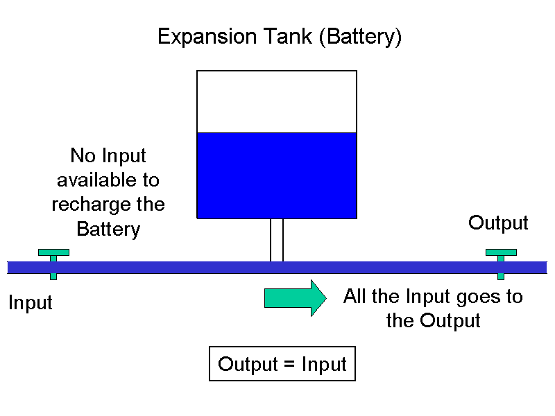
When the output matches the input, the tank stops filling because all the input is being diverted to the output. Again, there is no 'simultaneous charge and discharge' - the battery just remains at it's current charge level.
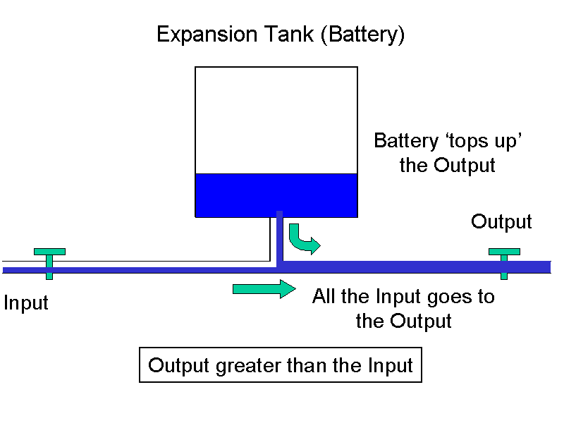
Now the case where the output exceeds the input.
Not only is all the input going to the output, but some of the stored water in the tank is needed to 'top up' the output. This means the tank starts to empty (the battery discharges)
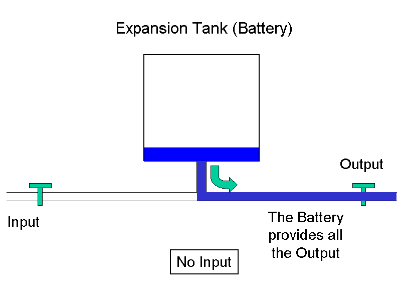
Finally, if there is no input, all the output has to come from the tank (battery) which continues to supply water (power) until it's empty.
At no point is it possible for water (power) to be flowing "into and out of the tank (battery) at the same time" :-)
This note last modified: 26th Sep 2016 12:20.
For more on building a Pi UPS, see my Pi UPS Project
