

What's a 'Barn Door' ?
The 'BarnDoor' (also known as a 'Scotch' or 'Haig' mount), is basic star tracking 'platform' that can be built using simple wood-working skills and used to mount a camera with zoom lens (or even a small telescope) for astrophotography.
Why do we need a 'star tracking' mount ?
It is quite possible to photograph the Moon** using a standard zoom lens, so long as a tripod and a cable release is used (to eliminate camera shake).
**A full discussion of moon photography is beyond this article, however a 300mm lens fitted to a digital camera (at max zoom) is about the minimum required to get decent shot (even then the Moon will only fill about 15% of the frame).
The general 'rule of thumb' for full Moon exposure setting when using a 300mm lens is known as the '100 16 rule' i.e. ISO 100, 1/100 second, f/16. For a half moon, halve the F or speed, or double the ISO (i.e. 1/100s, 100iso f/8 or 1/50s, 100iso, f/16 etc)
Most digital camera's will not find enough light for their automatic focus systems (although you may be lucky with a full moon and a 'fast' lens). In any event, you will soon find how difficult it is to focus on the Moon manually (especially with modern lenses that allow you to focus 'beyond infinity'). It is thus recommended that you choose the highest ISO and smallest aperture (highest f number & thus greatest depth of field) possible. Since an 'out of focus' result is far worse than any ISO 'noise' (for a full Moon thats 1/1600s f/32 @ 800 ISO = which will usually be better than 1/400s, f/16 @ 400 ISO).
To photograph stars requires longer exposure times and unless some means of tracking the stars is used, your photos will show visible 'star trails' (streaking). The higher your 'magnification' (i.e the more powerful your camera lens) the sooner star trails will start to appear.
Stars near the north 'move' very slowly (Polaris, the 'north star', is virtually stationary) whilst those near the horizon will speed across your field of view at a rapid rate.
The 'vertical' position (or 'how far North') of a star is called it's 'declination' .. those 'straight up north' (such as Polaris) are at 90 degrees (straight up) whilst those 'on the horizon' are at 'zero'.
In practice, unless you are observing out to sea, the horizon will be obscured by trees, houses and hills .. and (at least in UK) light pollution or 'sky glow' means there is no point in trying to photograph anything with a Declination lower than 30 degrees or so.
How long before you see 'trailing' ?
The 'time to trailing' for typical lens sizes is plotted below against star Declination.
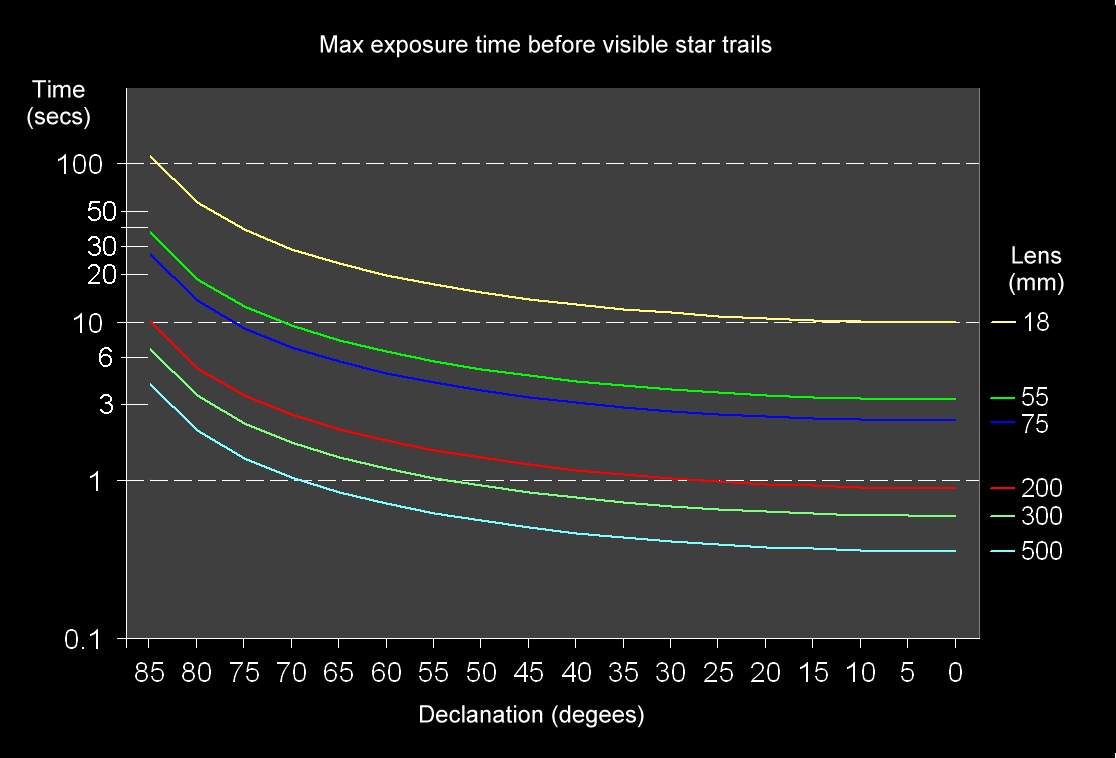
Note the chart (left) is based on the 'rule of thumb'
max. exposure time = (1000 * max. trail (microns) / 36) / (focal length * Cosine(declination)). Max. star trail has been set to 1 pixel for the Canon 350D = 6.5 microns.
For a list of popular digital camera pixel sizes, see here
In practice, the max. exposure time before visible streaking starts to show also depends on the aperture (f/ number) and the 'film speed' (ISO).
To do your own calculations of star trail lengths, I suggest a visit to
Wilmslow Astro.
Another 'rule of thumb' when photographing the stars is 'all the 4's' i.e. at f/4, ISO400 you will need an exposure time of 40s. From the above chart to avoid star trails at 40s exposure time you must only use lens 18-55mm (and even then you have to be pointing your camera virtually straight up i.e. 75-85 degrees Declination).
Of course if you can boost your ISO 4x to 1600, the time reduces 4x (40s > 10s) and at the 10s limit you can use your 18mm lens across the entire sky ... but even the smallest telephoto (200mm, red line) will show trails greater than 1 pixel unless aimed almost straight up (85+ degrees Declination).
What are the different types of Barn Door platforms ?
The operating principle is shown in the Basic 'tangent' drive diagram below
 (to skip this overview and check out the final design I decided to do for, go to page 2 (click 'Next>>' in the Navigation Bar on the bottom left).
The two green 'arms' (planks of wood) shown left are connected by a Hinge.
The Drive shaft (the screw bolt) is threaded through the Base (static) arm so as to push against the Top (movable) arm.
As the Drive (screw bolt) is turned, the Top arm is pushed upward (or allowed to drop down) in the direction of the (blue) arrows shown.
In operation, the whole apparatus is 'tipped up' toward the viewer and fixed at an angle determined by your latitude so that the Hinge can be aligned with the Earths axis of rotation by pointing it directly at the Pole Star (i.e. North)
Thus, when the Drive is turned at the correct rate, the Top arm will move so as to counter-act the Earths rotation. A camera (or small telescope) fixed to the moving Top arm will then 'track' the stars.
A typical Basic Tangent drive is seen to the right.  Here the two arms are held together with elastic bands (grey, seen fitted to far left hand end of the arms). A wooden wheel (with a white graduated scale) has been attached to the end of the Drive screw bolt to assist manual drive.
As with most Barn Doors, the arms have been constructed in such a way that the Drive screw rod needs to be turned at (exactly) 1 rpm.
To achieve this, the user turns the Drive wheel to follow the second hand of a wrist-watch (which can be seen 'clipped' to the bottom arm, & positioned between the drive wheel & elastic bands). The wheel is marked in 'seconds' (one complete turn = 60 seconds).
The whole apparatus is fixed to a tripod allowing it to be tipped up for Pole Star alignment.
Solving problems with the Basic Tangent Drive.
Close examination of the diagram & example above will show that the Basic 'tangent' drive system suffers from 2 problems. Both are associated with the simple nature of the screw rod Drive system.
1) As the Drive rod is turned, the top arm moves in an arc (as shown by the blue arrows in the diagram above) centred on the Hinge. As a result, the top end of the Drive rod will be 'sliding' against the bottom of the Top arm - and this can cause sufficient vibration to ruin your photos.
This first problem can be solved by pivoting the drive screw mounts  (grey blocks, shown in the Isosceles Drive diagram left).
In the diagram, the top end of the Drive screw bolt is fixed (eg. via a ball race) into the top pivot block.
The Drive screw bolt is then threaded through the bottom pivot block and can be turned (manually) from below.
As the arms open (or close), the pivot blocks turn to follow changes in Drive screw angle (and avoid any slippage against the top arm)
In the actual build example right,  from
from
Since the Motor is fitted to the bottom end of the screw rod, this now becomes the fixed end. So the Top arm is threaded through a fixed nut in the top pivot black allow the arm to 'ride up' on the rotating screw rod.
Note - it doesn't matter exactly where the camera is mounted - it just has to be turned through the correct angle.
2) A more difficult problem is that, if the bolt is turned at a constant speed, then the Top arm will actually slow down as the 'BarnDoor' opens (or speed up as it closes). This means that, even if the system is correctly calibrated at 1 rpm for some specific start position, the longer it is driven, the more the Top arm will be in 'error' at tracking the stars.
The tracking error can be reduced by adding a second Top arm - which is 'driven' up and slides along the first - thus creating a Double Arm (Haig) Drive. However building a Double Arm Drive is no longer the simple proposition we started with. An alternative to Double Arm Drives is to vary the drive rod rotation rate - again not so simple if you intend to 'drive' the system manually.
Arc Drives
Returning to basic principles, we see that both the 'sliding' and vibration caused by the rotating screw bolt (and the drive error) can all be avoided if a fixed, curved rod is used - and movement achieved by turning a Drive 'nut'.
In the diagram shown (left)
 the curved rod is fixed at the top end arm.
The arms will be pushed apart as the Drive (nut) running on the curved rod is turned clockwise. As the nut is turned anti-clockwise it will 'run up the screw thread' - and the arm weight (with elastic band assistance, if necessary) will push the arms closed again
Any friction between the rotating nut and bottom arm can be minimised by fitting a couple of polished (and oiled) washers between the (nut) and the lower arm.
 A 'half sized' arc-drive is shown below/right. Made from 'corrugated aluminium' this hand driven unit is mounted on a standard tripod and is highly portable.
Since all the dimensions have been halved, the Drive Nut only needs to be turned at 'half a revolution per minute' i.e. the rotating 'nut' (fitted with a card 'wheel') will need to be turned once in 2 minutes.
Note the fixed angle brackets between the bottom arm and the tripod 'head'. Since the 'tip over' angle must match the Latitude of the observing location, the builder has chosen a 'compromise' making it suitable for N. America / Europe use - the precise angle required would be set by adjusting the tripod mounting head (or the length of the tripod legs)
A more 'general purpose' design for 'world wide' travel would be to eliminate the angle brackets and incorporate some angle measurement device (eg protractor & 'plumb bob)
The main problem with a half-size design is achieving the required 'drive' speed. In the full size design, 'one revolution per minute' is simple to achieve - you only need to practice 'tracking' the movement of the second hand of a watch. Achieving "half a rev. per minute" is a little more difficult !
Of cousre all 'hand operation' is difficult in the dark. Using a red light will preserve your 'dark adapted' vision but will 'fog' a long exposure image just as much as any other unwanted light.
So much for the basic design proposition - click Next>> (bottom of the Navigation bar, left) for the actual calculations ...