Current main topic notes (includes mini-projects, common circuits and common code snippits etc.)
(-) 6010 PC Parallel port pin out

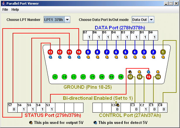
The Parallel port is a D-Type 25 Pin female connector. The connector supports 8 Data pins, 5 Status pins and 4 Control pins. Voltage levels are TTL (logic '0' 0v (<0v7), logic '1' 5v (>1v8 = some modern motherboards likley use 3v3 not 5v as Vcc). The other connector pins are all 'Gnd'.
Each of the pin sets (Data, Status, and Control) has a specific address assigned in sequential order. For example, if you set the Data port to the 'normal' LPT1 address 0x0378, the Status port is 0x0379 and the Control port 0x037A.
Originally, the Data port (Pins 2 through 9) was a 'write-only' port (i.e. limited to data output). However, in 'bi-directional' mode, the Data port becomes a 'read/write' port. The Status port (Pins 10 through 13 and Pin 15) is read-only. The Control port (Pins 1, 14, 16, and 17) are 'read/write'.
The Data Register
The IEEE-1284 standard refers to the Data lines as 'D1' through 'D8', however, to avoid confusion, I will use 'd0' to 'd7' which matchs the more normal usage (and matches the approach taken with the Status and Contol ports)

Thus pin2 = d0, through to pin9 = d7

The Status port
An 8 bit port (S0-S7) that 'senses' the state of the five Status pins on S3 through S7. S1 and S2 are unused, however S0 is a 'timeout' flag when the port is operated in EPP mode (when S0 can be written, i.e. cleared, by software).

In most implememntations, the Status pins are terminated with pull-up resistors (so all 5 pins default to '1' when nothing is plugged in)

S0: Timeout. In EPP (Enhanced Parallel Port) mode, this bit sets to '1' on a timeout of an EPP data transfer. Otherwise unused.
S1: Unused.
S2: Unused, except for a few implementations where this bit indicates the parallel port interrupt status (PIRQ). 0 = parallel-port interrupt has occurred; 1 = no interrupt has occurred. On these ports, reading the Status register sets PIRQ = 1.
S3: (pin15) /Printer Error (/Fault). Pulled Lo by the printer when it detects paper jam (or other fault condition).
S4: (pin13) Printer Ready. High when the printer is 'on-line', Lo when plugged in and powered on but not ready.
S5: (pin12) No Paper. High when the printer is out of paper (Lo when paper ready to print).
S6: (pin10) /dACK. Data acknowledge. Pulled Lo by the Printer to indicate it has accepted a byte. When interrupts are enabled, a transition (usually the rising edge) on this pin triggers an interrupt.
S7: (pin11) Printer Busy. Pulled Lo by the printer to indicate that it is unable accept any more data.

Note that, when the cable is out (or the printer is powered off), all the Status bits are 'Hi'. This signifies 'No error', 'Ready', 'No Paper)', 'no ack', 'not Busy' i.e. S5 is the only 'flag' that shows the printer is not ready to start printing !

The Control Register
The Control register sets the states of four Control bits, C0 through C3. Although used as outputs, on almost all implementations, the Control bits are 'open-collector' (or open-drain) driven, which means that they can also function as inputs.

C0: (pin1) /dRDY. Lo to indicate to the Printer that new data has been placed on the Data port. The Printer typically latches the state of the data lines at the end (rising edge) of this pulse.
C1: (pin14) /Line Feed (or /Auto-line feed). A low tells the printer to automatically generate a line feed (ASCII code 0Ah) after each Carriage Return (ASCII 0Dh).
C2: (pin16) /Reset. Pulses Lo to reset the printer (clear its buffer etc). The minimum pulse width is 50 microseconds.
C3: (pin17) /.
C4: Enable Interrupt. Set Hi to allow interrupt requests from /dACK (S6) to the PC’s IRQ (interrupt-control) circuits.
C5: Data I/O mode. Sets the direction of the Data port, 1=input, 0=output (note that the Printer Port has to be configured for bidirectional use in the BIOS (PS/2 mode) in order for this bit to have an effect).
C6: Unused.
C7: Unused (although in a few implementations, this bit is used instead of C5 for Data I/O setting)
This note last modified: 8th Feb 2018 14:59.