Links to all my notes (includes mini-projects and source code etc)
(+) 0001 How do I change the Pi System partition size ?
(+) 0100 Device tree settings
(+) 0201 Power over Ethernet - (PoE)
(+) 0202 Solar Power - (with WiFi)
(+) 0203 Power Bank pass through
(+) 0400 Accessing the SDHC card system image
(+) 0401 Accessing PC shares from the Pi
(+) 0402 Installing samba - (the Pi as a Network Share on your PC)
(+) 0900 Can this approach be scaled up to a PC UPS ?
(+) 1001 Pandora Spotify on the Pi
(+) 1002 Playing movies on the Pi
(+) 1003 Getting VGA from the HDMI socket
(+) 1004 Using the RCA socket
(+) 1005 Using the Pi RS232 serial links
(+) 1006 Using the GPIO pins
(+) 1007 Controlling the Pi Zero ACT LED
(+) 1200 List of standard camera modes
(+) 1300 Auto file names
(+) 6500 How to make the System partition read only ?
(+) 6501 Minimising SDHC corruption on power down
(-) 9000 diode switch
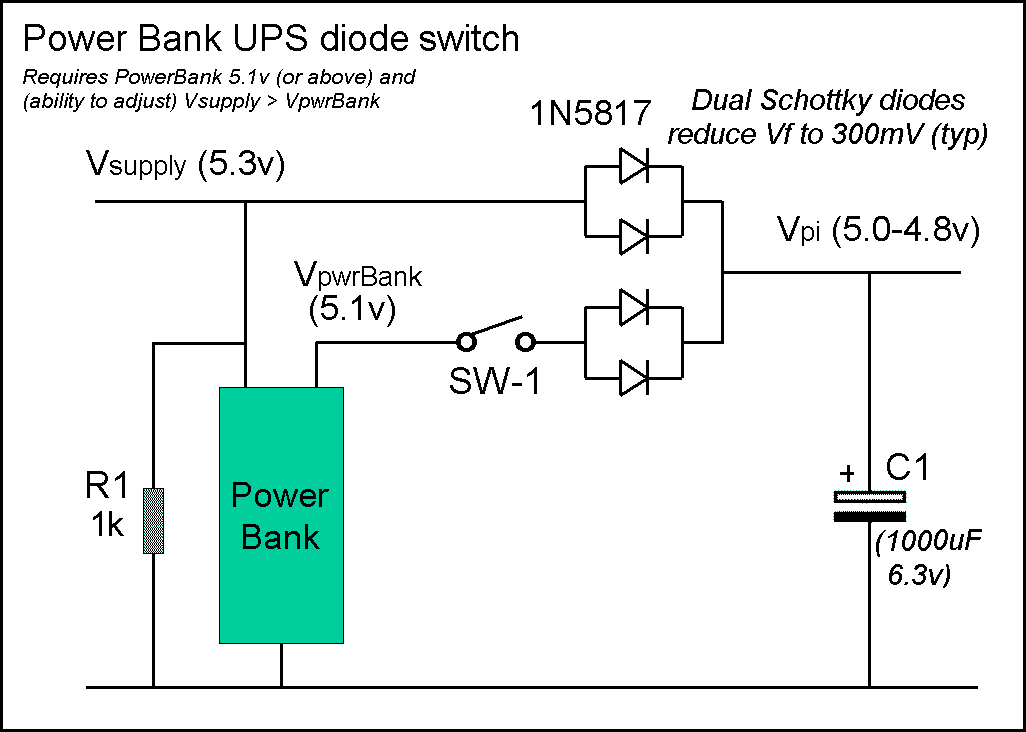
To back-up a CCTV Pi Zero + camera (using PoE), all you need is two pairs of diodes (pairs to keep down the Vf, as per above). When switching power it's always a good idea to add in a capacitor (or two) to prevent sudden voltage drops.

Of course, when using diodes, the Vsupply voltage must be greater than the Power Bank (VpwrBank) voltage to ensure Vsupply is used (rather than VpwrBank).
When PoE (Power Over Ethernet) is used, this is not a problem, as the PoE regulator output (= Vsupply) can always be set higher than VpwrBank.
In the example (left), if the PowerBank output is 5.1v, then the PoE regulator can be set to 5.3v (just to be safe).
The above works just fine so long as the PoE voltage doesn't have to be set so high that it exceeds the PowerBank input voltage tolerance.

SW-1 is provided so the PowerBank can be disconnected from the Pi and the Pi powered down without the need to unplug Vpi (in a Pi Zero CCTV system, Vpi is likely soldered direct to the Pi GPIO header holes so 'unplugging Vpi' isn't an option :-) ).

Note there is no provision to 'auto-disconnect' the PowerBank after Vsupply has been lost. This means it will keep providing power to the Pi until Vsupply is restored (or until it runs "flat", or until you manually open SW-1). To avoid flattening the PowerBank, the CCTV Pi software can be programmed to shut off the Pi after some 'reasonable' time (even a single cell 1700mAHr PowerBank should keep going for 6 hrs or so).

How the diode switch works
If the Power Bank has 'pass through' (or 'charge through') capability, it can be used without the need for any diode switching circuit. However 'charge through' PowerBanks tend to be aimed at the 'iPhone / iPad' user = so are expensive when compared to the basic £1 single cell unit now available (although a 'charge through' PowerBank is still about half the cost of a Pi 'Hat' UPS, mst of which don't even use rechargeable batteries !!)

For a basic Power Bank that doesn't support 'pass through' we can use a simple diode circuit so long as we can overcome the 'voltage problems'.

The voltage problem (part 1)

The forward voltage drop (Vf) of a 'typical' diode will be at least 0.6v. The Pi needs at between 4.75v (if it's to power USB (or HDMI) connected devices) to 4.65v (at which point the Pi issues it's 'low voltage warning'). So if we start with 5.0v and subtract the 'tryical' diode drop of 0.6v we end up at 4.4v and a non-working Pi.

Using a low Vf Schottky diode (such as the 1N5817) we can get the Vf(max) down to 0.45v (at 1A). Since Vf(typ) is 0.40v (at 1A) it might even be possible to test a 'batch' of diodes and select the 'best', however even at 0.4 that still only gets us 5.0-0.4 = 4.6v and a Pi with a 'low voltage warning' error at best.

To drive USB devices (or a HDMI to VGA converter) from the Pi, we need 4.75v or more. However diodes with a Vf of 0.25v at 1A don't exist, so we have to get clever ...

The voltage drop of a diode depends on the current passing through it.
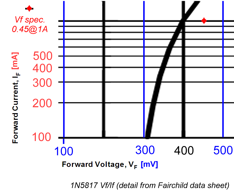
Shown right is a detail from the 1N5817 typical If/Vf curve (from the Fairchild data sheet). From this we see the typical Vf is 400mV (0.40v) at 1A, however at the more typical current of a Pi Zero (+ camera) of 250mA Vf is only about 330mV
If we wire two diodes in parallel and the current is shared, at 125mA, Vf is even lower (close to 310mV)
Since each diode will have slightly different If/Vf curve, there is no way to 'guarantee' equal current sharing, but what we can say is that the overall Vf will be the 'lower' of the Vf of the two diodes at whatever current each passes.

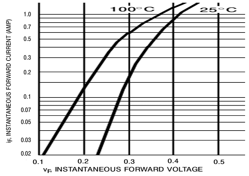
The Vf voltage drop also depends on the temperature of the diode
Shown left is the 1N5817 If/Vf curve at 100 degrees and at 25 degrees. Initially the diode with the lower Vf curve will pass most of the current, which means it will heat up first. This leads to a 'run-away' effect as the 'hot' diode's Vf falls further leading to it passing even more current.
For this reason, diodes in parallel normally need to be 'thermally coupled' - however at the sort of currents drawn by the Pi (250mA), diode heat dissipation will be minimal (250mA * 300mV = 7.5mW)
Two 1N5817 in parallel should guarantee Vf no more than 0.3v, which is fine for the Pi (5.0 - 0.3 = 4.7v (just above the 4.65v Low Violate warning :-) ) but 'marginal' for anything connencted to the Pi's USB (or HDMI) socket, in which case you need a PowerBank that outputs about 5.1v (3 bifferent brands I have ranged from 5.06v to 5.16v, so it's a reasonable guess most will be at least 5.05v).

The only way to do reduce Vdrop (the Vf loss) is to use a MOSFET (which exhibits a 'resistive Vf' at low Vds voltages). For example, for the IRLL014NPBF, the 'on' resistance is typically 0.2 ohm (at Vds 5v), so at 250mA the Vdrop should be in the order of 0.05v. However there is a problem with using a MOSFET = once it's 'on' it conducts in both directions ! This means you need some additional components (such as a Zener) that can be used to 'switch off' the MOSFET when the battery is not needed (see the "(+) MOSFET switch" note below)

The voltage problem (part 2)

The second part of the problem is what happens when Vsupply is unplugged. A PowerBank (without pass-through capability) typically has a simgle internal circuit that switches 'modes' between 'recharge' (power in) and 'charge' (power out). When in recharge mode (Vsupply present), they likely won't output anything at all. So when Vsupply is removed, it needs to fall to 0v as fast as possible (so the PowerBank can 'switch over' and power the Pi as fast as possible).

To ensure Vsupply is pulled to 0v when the voltage on the PoE cable is removed) R1 is used. C1 keeps the Pi powered whilst the PowerBank is 'taking over'. If the Pi crashes when Vsupply is unplugged, C1 can be increased (up to 10,000 uF or so) to keep the Pi going longer (and give the PowerBank more 'switching time') whilst R1 is reduced (no less than 100 ohms) so the PoweBank sees '0v' input faster.

Slow switch over is caused by Vsupply not 'decaying' fast enough - so if reducing R1 to 100 ohms doesn't work, try adding a Schottky diode between Vsupply and the PowerBank recharge 'input' (but do check that the PowerBank still recharges OK = most will be fine from 4.55v). The diode will isolate the PowerBank when Vsupply falls below 0.45v and 'guarantee' 0v is seen as fast as possible.

No matter what yu do, some ultra-cheap PowerBanks can take up to a second to 'switch over' and power the Pi. Using these for 'battery back-up' is a 'challenge' :-)

The voltage problem (part 3)

The final part of the problem has already been mentioned - the need for a Vsupply greater than VpwrBank to ensure it 'takes over' powering the Pi. In practice, it's quite possible that the PowerBank will shut off it's output as soon as it 'sees' an acceptable (or any) voltage at it's input, in which case Vsupply has to 'take over' as soon as the PowerBank shuts off it's output.

The 'no load' output of 8 different PowerBanks were found to be :- 5.02, 5.04, 5.07, 5.09, 5.12, 5.14, 5.14, 5.15

C1 should ensure the Pi keeps running if the PowerBank shuts off before Vsupply rises to 5.0 volts (and supplies the Pi with > 4.75v). If not, try increasing C1 to 10,000uF to give it more time.

Note that high values of C1 means high 'inrush' currents when power is first applied. Whilst the diodes should survive, unless Vsupply is already present when SW-1 is closed, the PowerBank might see a 10,000uF (or even 1,000uF) C1 as a 'short circuit' and 'cut off' automatically (LiPo batteries have current limits - drain them too fast (or charge them too fast) and they catch fire - to stop this the internal circyuit will 'cut off' the load :-) ).

Whilst this is not a problem for CCTV (when you only need the UPS to 'keep the camera going' after the PoE power is lost), it's a bit of an annoyance if you want to use the UPS to power the Pi 'in the field' without any possibility of Vsupply. If this happens, you can try reducing C1 (to the point where the Pi crashes when Vsupply is removed)
This note last modified: 29th May 2018 14:36.